On page #35 of the nhx manual it mentions 120/208 three phase but didn't see it in the settings, which I could have easily overlooked .


You are using an out of date browser. It may not display this or other websites correctly.
You should upgrade or use an alternative browser.
You should upgrade or use an alternative browser.
New 10kw NHX AIO From Watts247
- Thread starter Kornbread
- Start date
Yes
I saw this menu option in the Growatt and it got me asking if the NHX has similar option.
Yes, you are right. I saw it in the manual to, but as my inverter is not yet in my hands, I can not confirm.On page #35 of the nhx manual it mentions 120/208 three phase but didn't see it in the settings, which I could have easily overlooked .
I saw this menu option in the Growatt and it got me asking if the NHX has similar option.
Attachments

Adam De Lay
Solar Wizard
18.6W when in standby modeWhat is the idle consumption on the unit in your video?
76.5W when system is inverting power
Edited to reflect watts instead of volts...
Last edited:
I presume you mean watts.18.6V when in standby mode
76.5V when system is inverting power
1.8 KWH per day when operating on battery based on the above numbers.
Mike C.
Adam De Lay
Solar Wizard
Bah, yes. Watts. Sorry...I hadn't had my coffee yet.I presume you mean watts.
1.8 KWH per day when operating on battery based on the above numbers.
Mike C.
Adam De Lay
Solar Wizard

The 3 phase diagram is in the manual.There is an option for 120/208V three phase output (2/3) on these inverters
To be1 to 1 compatible with my grid type I need to change the Line voltage to 127V so I can get 127/220V three phase for the backup loads.
Do you guys happens to know if such change/setting is possible? Maybe via an installer app?
The AC input voltage limits for low and high look like they would encompass your range of operation, but this is not explicitly clear. You are only abut 5% off the 120/208 voltage. Why do you need 127/220 3 phase?
A potentially concerning note with 3 phase operation was this:
"PHASE A/B/C: This interface is used to select the output phase of the device when three phases are used. (Reserved function)."
When I see "Reserved function", I translate that to "not yet implemented" but maybe it just means this setting is automatic and you don't have to set it manually.
When the grid is down, my expectation is that the units will produce 120/208 3 phase power, when the grid is up, they will sync to the 127/220 3 phase input. I would surmise that is reasonable enough.
I have no idea if the units actually work on 3 phase, so the above is just manual reading plus engineering intuition.
Mike C.
Excellent.Thanks to @mciholas, I have Solar Assistant working on the NHX. Thanks for finding the proper connector!
The connectors are:
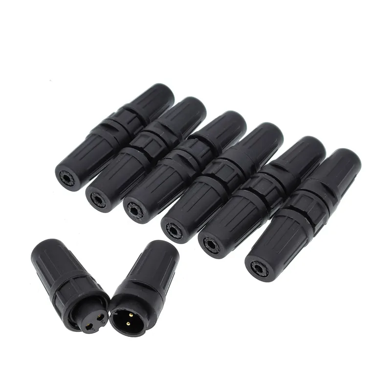
1.03US $ 25% OFF|PY07 Z108 Waterproof Connector Docking Plastic Aviation Plug Bayonet Socket IP67 Butt Connector 2pin 3pin 4pin 5pin 6pin 7pin| | - AliExpress
Smarter Shopping, Better Living! Aliexpress.com
Choose the 4 pin bayonet style. They are sold as a male/female set.
The two uses will be to either make a Solar Assistant cable that doesn't have to go internal to the machine, or to build an extension cable so the included Wifi module can be moved to a better location (for example, not inside a wiring trough).
For SA, you need to hook to the RS485 A and B lines, plus GND.
For a Wifi extension cable, you need to run all four wires between connectors.
As for the pin out, I've seen two different versions.
This is from the Solarman website:

This is from the Solar Assistant website:

Not the same!
I would verify by measuring continuity from GND to other grounds in the inverter, and then measuring 5 volts appears on pin 1 just to make sure you got it right. Once you do, let us all know what the actual true pinout is.
Mike C.
Adam De Lay
Solar Wizard
I used the one from Solar Assistant:Excellent.
The connectors are:
1.03US $ 25% OFF|PY07 Z108 Waterproof Connector Docking Plastic Aviation Plug Bayonet Socket IP67 Butt Connector 2pin 3pin 4pin 5pin 6pin 7pin| | - AliExpress
Smarter Shopping, Better Living! Aliexpress.comwww.aliexpress.com
Choose the 4 pin bayonet style. They are sold as a male/female set.
The two uses will be to either make a Solar Assistant cable that doesn't have to go internal to the machine, or to build an extension cable so the included Wifi module can be moved to a better location (for example, not inside a wiring trough).
For SA, you need to hook to the RS485 A and B lines, plus GND.
For a Wifi extension cable, you need to run all four wires between connectors.
As for the pin out, I've seen two different versions.
This is from the Solarman website:
View attachment 216011
This is from the Solar Assistant website:
View attachment 216012
Not the same!
I would verify by measuring continuity from GND to other grounds in the inverter, and then measuring 5 volts appears on pin 1 just to make sure you got it right. Once you do, let us all know what the actual true pinout is.
Mike C.

Now I only ended up using pins 2 and 3. I checked pin 4 for ground continuity and there was none. Tried between the ground bus bar inside the unit as well as the ground stud directly behind the COM port on the bottom of the inverter.
Curious. I will investigate on my unit when able.Now I only ended up using pins 2 and 3. I checked pin 4 for ground continuity and there was none. Tried between the ground bus bar inside the unit as well as the ground stud directly behind the COM port on the bottom of the inverter.
Is pin 2 ground? Due to the way RS 485 works, it is sometimes possible to get good data even if only one line is wired up. Maybe the SA website is wrong and it "just works" any way. The signal margins will be compromised if using only one signal, but maybe that's enough.
Since Solarman makes the Wifi adapter, and the SA website is technically for the Megarevo (assumed to be compatible, but maybe not), maybe the Solarman website is more correct.
Mike C.
Adam De Lay
Solar Wizard
Nope, pin 2 is not ground. Before I found that diagram on the SA website, I tested all 4 pins for ground and none of them toned out.Curious. I will investigate on my unit when able.
Is pin 2 ground? Due to the way RS 485 works, it is sometimes possible to get good data even if only one line is wired up. Maybe the SA website is wrong and it "just works" any way. The signal margins will be compromised if using only one signal, but maybe that's enough.
Since Solarman makes the Wifi adapter, and the SA website is technically for the Megarevo (assumed to be compatible, but maybe not), maybe the Solarman website is more correct.
Mike C.
Hedges
I See Electromagnetic Fields!
- Joined
- Mar 28, 2020
- Messages
- 21,208
Because RS485 is differential, it has a pretty good chance of working without a proper ground routed together with data. Different devices could be floating at a voltage where data gets through (bumped back into line by ESD clamping at the rails), or could be grounded through other structures & cables.
Would be more reliable with ground reference. +5V, if present, could also provide reference but is less likely to be solidly connected at both ends.
But note that "ground" in a data bus is not necessarily same as "chassis", and this confusion is often a reason for EMI failures. It likely means reference plane of PCB. Do you measure voltage between it and +5?
Adam De Lay
Solar Wizard
Pins 1 and 4 together show 5v.Because RS485 is differential, it has a pretty good chance of working without a proper ground routed together with data. Different devices could be floating at a voltage where data gets through (bumped back into line by ESD clamping at the rails), or could be grounded through other structures & cables.
Would be more reliable with ground reference. +5V, if present, could also provide reference but is less likely to be solidly connected at both ends.
But note that "ground" in a data bus is not necessarily same as "chassis", and this confusion is often a reason for EMI failures. It likely means reference plane of PCB. Do you measure voltage between it and +5?
I would like to say thank you to all who have posted info about the NHX inverters. I have been monitoring this thread since beginning of April and it has been very helpful. I self-installed a 24 panel ground mount system at my home 2 years ago. The inverter was an SMA grid-tie 7.7KW. In two years of running I had zero problems with the SMA but I wanted to add battery so I started looking to see what was available that I could afford. The SMA had 3 MPPT's so I have 3 strings of panels and I really wanted to stay with that configuration of 3 strings. There was not much I could find that had the number of MPPT's and voltage range I was looking for so when I found this thread about the NHX I became very interested. Besides having 4 MPPT's I also really like having a generator input built in.
I pulled the trigger and ordered a 10K NHX and 2 SOK server rack batteries from Watts247. I swapped out the SMA inverter for the NHX and as of today it has been running in grid tie mode for 2 weeks. I am happy with it - no issues so far. The inverter is mounted under my ground mounted array. I still need to put in a concrete slab and a weather enclosure behind the inverter before installing my batteries and my generator.
Thank you to Mike C for finding the comm connector. I will be ordering one of them.
Attachments


The 3 phase diagram is in the manual.
The AC input voltage limits for low and high look like they would encompass your range of operation, but this is not explicitly clear. You are only abut 5% off the 120/208 voltage. Why do you need 127/220 3 phase?
A potentially concerning note with 3 phase operation was this:
"PHASE A/B/C: This interface is used to select the output phase of the device when three phases are used. (Reserved function)."
When I see "Reserved function", I translate that to "not yet implemented" but maybe it just means this setting is automatic and you don't have to set it manually.
When the grid is down, my expectation is that the units will produce 120/208 3 phase power, when the grid is up, they will sync to the 127/220 3 phase input. I would surmise that is reasonable enough.
I have no idea if the units actually work on 3 phase, so the above is just manual reading plus engineering intuition.
Mike C.
The normal grid where I am situated is a 3phase system with 127V line voltage, between two lines 220V (Wye connection).
Currently running offgrid with two inverters in splitphase mode so for my appliances it's all the same.
Lately decided for a hybrid inverter with sell capabilities and found the NHX. I did see the 3 phase diagram with 3 inverters but for starters (experimenting) I will use 1 inverter and configure it to put out 120/208V and connect two lines from the grid on it.
You are indeed right that itś only 5% difference with the grid here and that it probably follow the grid and should work.
As soon as I get the inverter, will test the grid interaction and if positive I will add more for a proper 3 phase installation.
Thanks for the explanation and thoughts...
One of them has to be ground, so your test isn't working. You might not be testing against the interface ground rail.Before I found that diagram on the SA website, I tested all 4 pins for ground and none of them toned out.
Mike C.
agarg
New Member
It is a repeat of what others have said but this sounds too good. 10Kw, split phase, all in one...
Although, I wonder how much will it be able to balance the split phase loads? 10KW will need a sizable autotransformer (at least a 50 amps to leave some headroom).
Although, I wonder how much will it be able to balance the split phase loads? 10KW will need a sizable autotransformer (at least a 50 amps to leave some headroom).
The pricing is not that far off other similar spec'ed units so the feature set is not that implausible.It is a repeat of what others have said but this sounds too good. 10Kw, split phase, all in one...
The inverter is two 5 KW 120 VAC inverters internally. There is no autotransformer.Although, I wonder how much will it be able to balance the split phase loads? 10KW will need a sizable autotransformer (at least a 50 amps to leave some headroom).
A video of various load tests:
Not exactly done with scientific vigor, but the unit does seem to handle significantly unbalanced loads.
Mike C.
Zwy
Emperor Of Solar
No auto transformer, not needed. Designed as a 240V split phase inverter.It is a repeat of what others have said but this sounds too good. 10Kw, split phase, all in one...
Although, I wonder how much will it be able to balance the split phase loads? 10KW will need a sizable autotransformer (at least a 50 amps to leave some headroom).
Surge capability. The only thing I can compare it to is the growatt spf60000t, and the spfxxxxt line is known to have good surge ability. Was cutting and welding on some scrap metal building a box, of sorts, to provide extra shelter for the combiner boxes while mounted on the pole mount support pole. The nhx is not connected to grid.
No issues using an angle grinder, all the lights, and the air compressor kicking on.
The plasma cutter is 240v and the only style plug that fits it was being fed by grid, so no test there. The plasma cutter does require the 3hp air compressor to run, which is on the nhx and had no issue starting repeatedly under load.
The autoarc130 (brand) 110v mig welder (older transformer style) would occasionally overload the growatt when set to high. Initially started welding with it on high but quickly lowered the heat as the metal was thin. No issues with the nhx.