diy solar

diy solar

Using solar micro inverters with batteries instead of panels

My thought would be emulate the I-V curve of PV panel, varying the power available to microinverter.
If you found a DC/DC supply with CV/CC output, you could have a PID or other control loop varying CV setting with the goal of keeping a CT (x V) on utility connection around zero amps & watts.

But likely not cheap to get several hundred watt DC/DC supply. Custom designs would be used for a product like this, and for one-off experimenting it would be time consuming and likely expensive.

PWM between two voltage sources (battery and capacitor) would have repeated capacitor charging inrush. So an inductor and diode is used in a boost converter. Voltage difference and PWM duty ratio determines current draw.

Easier would be to have a bank of microinverters, and enable more/fewer of them.

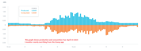
For sure it would be much more simple to have a bank of inverters, but the reality is my overnight/background consumption is below that of even one microinverter if you look at the circled overnight area - the graph shows 5 days of my net power use - up is fed back to the grid, down is consumption from the grid.
The big use spikes are electric cooker/hob/microwave/kettle etc. I am not aiming to be able to cover those, i just want to reduce my background use to zero when i have sufficient solar stored. If you resolve the data a good half of my cost is attributable to this background use!

Now i've seen the inverter will run at lower power off a current limited PSU it must be possible.....I've ordered a PWM module to have a go with - it is supposedly capable of 15A but i should only need to go to 10 at most. It cost £10 including delivery so i'm not expecting miracles but it's worth a try. In terms of inrush current, when the cap is fully discharged (system off for a while) the inrush will be high so i may have to implement a soft start to save the PWM module, but when it's running the inrush should be small - the cap voltage will only have time to decay a small amount below Vbatt before it is recharged - the PWM unit is ~16kHz so plenty quick. The capacitor is hopefully acting more like a low pass filter to smooth the PWM out before it gets to the inverter....

This particular PWM module is also interesting to me because it has a 5v input for control which will work nicely with my arduino control system if i can get it working OK with the inverter.
I won't get the bits until the middle of next week at the earliest but i'll post again with an update whichever way it goes!
 

Attachments

  • 5 days use.PNG
    5 days use.PNG
    55.5 KB · Views: 10
  • PWM1.PNG
    PWM1.PNG
    489.1 KB · Views: 11
  • PWM2.PNG
    PWM2.PNG
    34.4 KB · Views: 11
Hello Meetyg,
You were right. ("I wouldn't do it")

I know this reply, to this part of your assistance, is a long time coming.

There are many types Buck Converters I have tested.
Only one is working.
I bought 3 of the particular type that worked and, of them, only 1 worked properly.
No buck converter has fried my batteries or the MicroInverter.
I have stopped using them & I don't recommend them.
Locking was not a problem & the output kind of fluctuated initially but settled down.

I just found the potentiometer current adjustment too flaky on all of them.
The buck converters were all an extra I just did not need.
Thy have their place but, just not in this situation IMO.

So...Thanks very much!
I did look at buck/boost converters to do the modulation but too many reports like this saying the cheap ones are pretty flaky at best - we'll see if the PWM works.
 
Thanks for this, i have now got the inveter running off a power supply on the bench. It is a little different in the UK, i use L1 and N at 240v for the single phase supply here. As i'm just bench testing at the minute i've just used 4mm plugs on the DC side but it will all get proper connectors on the final system - which will almost certainly be indoors anyway.

In the attached photo the PSU is set to 23v and also current limited to ~2.6A - when the inverter goes active the voltage fluctuates a little bit and the PSU is moving between CV and CC mode - i guess this is the MPPT doing it's thing. It does show that it is possible to run the inverter below full power somehow - i just need to mimic the PSU!
Do you have any way to measure the stability of the current output from your PSU once it has stabilized?

I’m curious whether a PSU feeding a Microinverter provides a relatively ‘safe’ / stable way to deliver a programmable amount if export from a Microinverter.

The claim is that the low-cost programmable DCDC boosters do not deliver a stable current but I’m hoping they are as stable as an AC-powered PSU…
 
Thanks for this, i have now got the inveter running off a power supply on the bench. It is a little different in the UK, i use L1 and N at 240v for the single phase supply here. As i'm just bench testing at the minute i've just used 4mm plugs on the DC side but it will all get proper connectors on the final system - which will almost certainly be indoors anyway.

In the attached photo the PSU is set to 23v and also current limited to ~2.6A - when the inverter goes active the voltage fluctuates a little bit and the PSU is moving between CV and CC mode - i guess this is the MPPT doing it's thing. It does show that it is possible to run the inverter below full power somehow - i just need to mimic the PSU!
Going well. I like what I see!
 
Now i've seen the inverter will run at lower power off a current limited PSU it must be possible.....I've ordered a PWM module to have a go with - it is supposedly capable of 15A but i should only need to go to 10 at most. It cost £10 including delivery so i'm not expecting miracles but it's worth a try. In terms of inrush current, when the cap is fully discharged (system off for a while) the inrush will be high so i may have to implement a soft start to save the PWM module, but when it's running the inrush should be small - the cap voltage will only have time to decay a small amount below Vbatt before it is recharged - the PWM unit is ~16kHz so plenty quick. The capacitor is hopefully acting more like a low pass filter to smooth the PWM out before it gets to the inverter....
Curious as to your results testing a PWM module. You can probably just add a parallel resistance of the appropriate size to precharge the output.

By design, a PWM module is not going to be able to deliver a stable current to a Microinverter so I’m interested in what level of current stability you get and whether you add additional capacitance to the output to reduce voltage ripple.

The concern that has been expressed is that current ripple beyond that delivered by solar panels can result in Microinverter input capacitors heating up and aging prematurely.

I guess we need someone to put a scope on both a solar panel feeding a Microinverter as well as one of these PWM modules feeding a Microinverter t understand what order of magnitude we are talking about and whether there is any real reason to be concerned…
This particular PWM module is also interesting to me because it has a [b{5v input for control[/b] which will work nicely with my arduino control system if i can get it working OK with the inverter.
I won't get the bits until the middle of next week at the earliest but i'll post again with an update whichever way it goes!
Is duty cycle controlled by voltage or by resistance?
 
Curious as to your results testing a PWM module. You can probably just add a parallel resistance of the appropriate size to precharge the output.

By design, a PWM module is not going to be able to deliver a stable current to a Microinverter so I’m interested in what level of current stability you get and whether you add additional capacitance to the output to reduce voltage ripple.

The concern that has been expressed is that current ripple beyond that delivered by solar panels can result in Microinverter input capacitors heating up and aging prematurely.

I guess we need someone to put a scope on both a solar panel feeding a Microinverter as well as one of these PWM modules feeding a Microinverter t understand what order of magnitude we are talking about and whether there is any real reason to be concerned…

Is duty cycle controlled by voltage or by resistance?
According to the spec sheet and label on the board it is voltage controlled...a big reason I want to try this one.

I like the idea of a parallel resistance to precharge the output...I have planned on capacitors to smooth the output, doing a very quick calc using 24v, 10a and 1/15000s I get 0.02j per cycle, so I've picked electrolytic caps that store 10x that energy: 1000uf, and I've ordered 5 of them...I'm hoping that 5percent ripple is ok for the inverter but I'll find out one way or another...


I've not got a scope although I can probably borrow one if I can't get it working very easily.
 
Do you have any way to measure the stability of the current output from your PSU once it has stabilized?

I’m curious whether a PSU feeding a Microinverter provides a relatively ‘safe’ / stable way to deliver a programmable amount if export from a Microinverter.

The claim is that the low-cost programmable DCDC boosters do not deliver a stable current but I’m hoping they are as stable as an AC-powered PSU…
I've only got the current reading on the PSU for now.
I think providing you jam enough capacitance to smooth the output it should be ok... providing the extra capacitance doesn't resonate at any point! I'm hoping it'll be fine as all the control circuitry is designed to switch at high frequency and the big capacitors I'm using should be way below that.
 
I assume you have a grid connection in order to enable the micro inverter to work. It needs 240 volt AC from the grid in order work. I don't understand what the buck converter is for?
I hear you. Other posts on this & other forums said connecting the microinverters directly to the battery would fry them.
So I was trying to control the current. All my inverters are connected directly to a 24v battery & are perfectly fine.
I have had one working with a buck converter for nearly 2 years now.
All the work I did in that area was great fun but somewhat misguided.
Yes I only do grid connect.
I would never, ever do off grid unless I absolutely had to.
I assume your goal is to harvest solar and produce AC or DC to power either a 24 volt DC device from the battery battery or some 120 or 240 volt AC device. That use case will determine which components you will need.
If you read this thread from the beginning, you will see several variations on this concept and no working examples.
I have been producing ~12KW of battery power per night for over a year now very cheaply.
I have ~18KW of batteries working faultlessly.
My abilities in this area were limited when I first started. I read this and other threads to start with and had much advice from many sources so at times I was fairly confused.
 
I've been analyzing this off and on too, don't have all the hardware necessary to experiment yet.

Seems that adding switching to the DC side would really end up requiring a current limiter of some sort to avoid blasting the microinverter capacitors during precharge. The available current for precharge will be many orders of magnitude higher for a battery than for a solar panel, even if solar panel were switched with full illumination. And typically a solar panel will start up slowly in the morning.

How harmful is switching the AC side?
The Enphase M215 inverters I use.
You can connect directly to battery. No problem.
I have other posts on this.
.Setup 3.JPG
 
How do you handle precharge surge? It's necessary to handle with a full size inverter so I imagine it is a higher risk on a microinverter.

When I game it out in my head, one would want to use a precharge resistor and then permanently connect the battery to the microinverter so that there is never again a large voltage imbalance.
 
B
How do you handle precharge surge? It's necessary to handle with a full size inverter so I imagine it is a higher risk on a microinverter.
There is no surge. The MPPT? seems to fill the microinverter slowly.
After about 5 minutes the green light comes on on the Enphase & it fires up.
Enphase uses microinverters on their battery systems. They just stack them together.
When I game it out in my head, one would want to use a precharge resistor and then permanently connect the battery to the microinverter so that there is never again a large voltage imbalance.
I have tried resistors.
They just get really hot & make no difference.
Some in this forum have made 24v batteries using AA batteries & tested that way.
I don't get your voltage imbalance question.
There is none that I have seen.
I charge the LiFePo4's up to 28.8 volts and they drop to ~24v after 14 hours.
(2x 24v 200ah)
On my posts I have already said I use one microinverter for 14 hours & the second for 7 hours. That gives me an average of 300w @ 240vac per hour for the whole night.
I have two of these setups the second inverter does the first 1/2 of the night on one. The other setup does the second half of the night.
Giving me 600w 240vac per hour all night.
 
B

There is no surge. The MPPT? seems to fill the microinverter slowly.
After about 5 minutes the green light comes on on the Enphase & it fires up.
Enphase uses microinverters on their battery systems. They just stack them together.

I have tried resistors.
They just get really hot & make no difference.
Some in this forum have made 24v batteries using AA batteries & tested that way.
I don't get your voltage imbalance question.
There is none that I have seen.
I charge the LiFePo4's up to 28.8 volts and they drop to ~24v after 14 hours.
(2x 24v 200ah)
On my posts I have already said I use one microinverter for 14 hours & the second for 7 hours. That gives me an average of 300w @ 240vac per hour for the whole night.
I have two of these setups the second inverter does the first 1/2 of the night on one. The other setup does the second half of the night.
Giving me 600w 240vac per hour all night.

The precharge resistor for string inverters is only used before the first time you plug in the battery. Will talks about it on his videos.

If one were to disconnect on DC side any input capacitors on the microinverters would eventually decay to 0V, so they would need to charge back up to battery voltage.

This is why I asked to confirm whether there is a daily DC side disconnect from batteries in your setup, since that would be a lot more stressful from a precharge angle.
Ahh. OK. I use Microinverters on my roof.
So all is 240v directly off the panels.
So I charge my batteries during the day off my 240v power.
Then I turn on the microinverters at night.
A number of times I have left the timer on all day and the microinverter has run 24 hours even with the charger being on all day.
It does not make any difference in that case to the microinverter.
It doesn't make any difference to the current the microinverter uses.
I get cheap microinverters here.
I have gotten about 70 for an average of about USD $27 each.
If you can afford to "burn" a couple have a try.
I have not been successful in doing so.
The only time I got the microinverter hot was when I had a buck (boost) converter in line & was boosting the voltage ~40v & the current.
 
Last edited:
Ahh. OK. I use Microinverters on my roof.
So all is 240v directly off the panels.
So I charge my batteries during the day off my 240v power.
Then I turn on the microinverters at night.
A number of times I have left the timer on all day and the microinverter has run 24 hours even with the charger being on all day.
It does not make any difference in that case to the microinverter.
It doesn't make any difference to the current the microinverter uses.
I get cheap microinverters here.
I have gotten about 70 for an average of about USD $27 each.
If you can afford to "burn" a couple have a try.
I have not been successful in doing so.
The only time I got the microinverter hot was when I had a buck (boost) converter in line & was boosting the voltage ~40v & the current.
Just to be sure you and zanydroid are speaking the same language, once your battery has been depleted to the point that you want to shut down a battery-powered Microinverter, do you do so by opening a relay controlling 240VAC grid signal reaching the inverter output (AC-switching) or do you do by opening a relay controlling 24VDC battery power reaching the Microinverters MC4 DC inputs (DC-switching)?
 
Just to be sure you and zanydroid are speaking the same language, once your battery has been depleted to the point that you want to shut down a battery-powered Microinverter, do you do so by opening a relay controlling 240VAC grid signal reaching the inverter output (AC-switching) or do you do by opening a relay controlling 24VDC battery power reaching the Microinverters MC4 DC inputs (DC-switching)?
OK. Many Thanks for assisting fafrd.
Sorry I misunderstood your question zanydroid.
I cut the DC side.
I don't use signals to control anything.
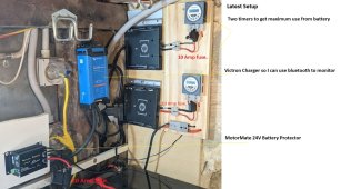
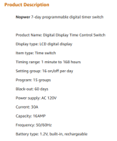
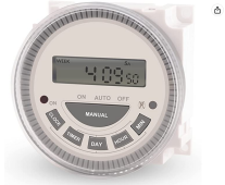
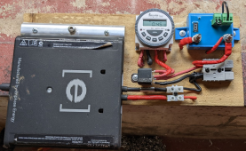
First - the timer Switch turns the DC on & Off. (It has a relay in it as per pic below)
_The first timer runs 14 hours.
_The second timer runs roughly 7 hours.
..........I set this to turn off the second MicroInverter BEFORE the MotorMate has to.
...........So between 5 & 7 hours.
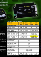
Second if that fails the MotorMate cuts the DC @ 23V
Third is the battery BMS itself.
Hopefully I have all you questions covered.

Re the Capacitors Decaying to 0volts - I really don't know.
I know when the capacitors in the MPPT fill up the MicroInverter starts producing continuously then.
Takes about 4 minutes which also tells me the MicroInverter is only taking what current it wants off the 24V battery.
After I cut the DC whether there is some residual current in the MPPT capacitors I don't know.
Whether it would drain to 0volts, if there was, I don't know.


1681710720177.png

1681711062782.png


1681711137669.png
1681719794715.png

1681720536397.png
 
Last edited:
Re the Capacitors Decaying to 0volts - I really don't know.
I know when the capacitors in the MPPT fill up the MicroInverter starts producing continuously then.
Takes about 4 minutes which also tells me the MicroInverter is only taking what current it wants off the 24V battery.
After I cut the DC whether there is some residual current in the MPPT capacitors I don't know.
Whether it would drain to 0volts, if there was, I don't know.

The several minute delay is software complying with rules regarding waiting for grid to be stable before operating.
Of course inverter only draws power as needed to deliver AC power. Except for charging capacitors, which just happens.

PV input to microinverter either hits a decoupling capacitor first, or an inductor first. I think it is capacitor.
Battery inverters have a large electrolytic capacitor bank, and when battery is first connected several thousand amps rush in for a millisecond, causing a large spark and sometimes blowing fuses or welding relays.
PV is a limited current source so only delivers a few amps.

If battery connected PV input of an inverter, would expect inrush current. Microinverter, smaller capacitors so less inrush.
This may cause stress to transistors in your Motor Mate. Closing circuit to an inductive load, there can be low power dissipated in the switch. Closing into a capacitive load, large current and power dissipation.

Circuits intended to precharge capacitors do so gradually, because power dissipated goes as current squared, and energy as current squared divide by time. Charging in 1/10th the time causes 10x the energy dissipation. But charging must be completed before load starts drawing DC current.

If yours has cycled a number of times without failure then it seems to have some margin. When we design something like this we try to keep current within max limits of the components.

Depending on no-load consumption by microinverter, I would have considered precharging it once, then switching AC side rather than DC.
 
OK. Many Thanks for assisting fafrd.
Sorry I misunderstood your question zanydroid.
I cut the DC side.
I don't use signals to control anything.
First - the timer Switch turns the DC on & Off. (It has a relay in it as per pic below)
_The first timer runs 14 hours.
_The second timer runs roughly 7 hours.
..........I set this to turn off the second MicroInverter BEFORE the MotorMate has to.
...........So between 5 & 7 hours.
Second if that fails the MotorMate cuts the DC @ 23V
Third is the battery BMS itself.
Hopefully I have all you questions covered.

Re the Capacitors Decaying to 0volts - I really don't know.
I know when the capacitors in the MPPT fill up the MicroInverter starts producing continuously then.
Takes about 4 minutes which also tells me the MicroInverter is only taking what current it wants off the 24V battery.
After I cut the DC whether there is some residual current in the MPPT capacitors I don't know.
Whether it would drain to 0volts, if there was, I don't know.


View attachment 145120

View attachment 145121


View attachment 145123
View attachment 145133

View attachment 145134
Thanks for the detailed reply. I’d thought you were switching AC so I’m glad I asked you for a clarification.

I assume you have a multimeter so if you’d like to put on a bit off effort to address the concerns being raised about precharge, perhaps you could measure the DC voltage on the output of the relay in the morning before it turns on.

If the leakage is so low that the Microinverters input capacitors maintain DC voltage close to battery voltage over the 4-8 hours the relay is open, the capacitors only charged once when you first connected the Microinverters.

If the DC voltage has dropped close to 0V just before the relay closes in the morning, then the capacitors are charging once per day but then the next question then becomes what guage of wire and total wire length do you have between battery and Microinverter input?

You obviously have had no issue for over 2 years now, so we are just trying to understand technically why that might be.
 
The several minute delay is software complying with rules regarding waiting for grid to be stable before operating.
Of course inverter only draws power as needed to deliver AC power. Except for charging capacitors, which just happens.
I really appreciate You & others assiting me.
PV input to microinverter either hits a decoupling capacitor first, or an inductor first. I think it is capacitor.
Battery inverters have a large electrolytic capacitor bank, and when battery is first connected several thousand amps rush in for a millisecond, causing a large spark and sometimes blowing fuses or welding relays.
PV is a limited current source so only delivers a few amps.
OK. Thanks I get it.
If battery connected PV input of an inverter, would expect inrush current. Microinverter, smaller capacitors so less inrush.
This may cause stress to transistors in your Motor Mate. Closing circuit to an inductive load, there can be low power dissipated in the switch. Closing into a capacitive load, large current and power dissipation.
OK. This is why the Victron Smart Battery Protect did not work.
I have a separate Victron Smart Battery Protect design that has a relay.
It works really well.
My later MotorMate design was to reduce complexity.
I could do the same with the MotorMate if it is better.
Maybe the 20AMP installed fuse might offer some resistance to the inrush current
.
1681780682122.png

Circuits intended to precharge capacitors do so gradually, because power dissipated goes as current squared, and energy as current squared divide by time. Charging in 1/10th the time causes 10x the energy dissipation. But charging must be completed before load starts drawing DC current.
I did not understand this before.
If yours has cycled a number of times without failure then it seems to have some margin. When we design something like this we try to keep current within max limits of the components.
My intricate design ability =0.
Dumb luck (after many burnouts) = >0
Depending on no-load consumption by microinverter, I would have considered pre-charging it once, then switching AC side rather than DC.
I worked on the DC side to make it "easier" for people without a lot of knowledge to have their own battery.
It was so others could do this with out touching the AC side.
zanydriod & fafrd - are suggesting it would be much better to switch the AC side.
I can see now that this is most likely true - I can do this sooner if others would like me to test it out.
I now get that if the inrush current is quite seldom rather than daily it will preserve the Battery Protect & the MicroInverter.


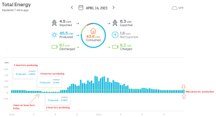
Note:
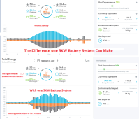
Even one makes battery a huge difference - see pic below.
Grid dependece can drop about 20%.
.
1681781916969.png
.
One Battery System.png
Thanks Again
 
Last edited:
It’s possible that, when the system turns back on again as charger turns on, the current limit on the charger will limit the inrush current at that time even if the capacitors have decayed away all charge.

I don’t have a full picture of how your specific setup works but this charger-based limiting idea (if it holds up) might be something others want to pursue, in combination with only switching on the AC side.

I’m curious if M250 and other microinverters report their idle DC side consumption. I’m not sure how much these would be optimized for AC down state, that’s supposed to be free power from the sun that would otherwise not be used.
 
Back
Top