diy solar

diy solar

6000xp with generic LifePO4 w/o communication

shayamip

New Member
Joined
Dec 31, 2023
Messages
25
Location
El Paso
I'm using 4x DC house 48v 50Ah batteries in parallel.

According to their specs:
Charging voltage: 58.4v
Operating range: 40-58.4v

1. How should I setup XP parameters according to this?
2. How does the XP keep track of SoC without communicating?
3. Is it possible to limit solar charge at 80% of Soc?

Thank you.
 
It can't track SOC. That is why you must use voltages instead of SOC when doing open-loop communication.

But these voltage numbers do change depending on the load and the charging rate right? Is there a way to compensate that?
 
In the settings you can choose all the voltage trip points.

Unfortunately, voltage is not a good SOC indicator for LiFePO4. About the only thing you can tell from voltage is when the battery is full or the battery is nearly empty. For all of the range in between, the only thing you can tell is that the battery is not full and not empty.

Sure. I have the smartshunt which give good SoC estimation. So, monitoring Soc is not a problem for me.

What I want from the inverter is that to stop charging the battery from PV at a certain level. Which parameter to change for that? I dont charge from the grid.
 
What I want from the inverter is that to stop charging the battery from PV at a certain level. Which parameter to change for that?
I plan to have the same set-up (48V LFP battery and 6000XP without communication).
I will set the voltage range in the inverter around 48V min and 56V max (3.0V-3.5V / cell).
So the battery BMS will take action if the voltage reach 40V (2.5V/cell) or 57.6V (3.6V / cell).

The only problem I can see in your case is if the BMS don't start to balance cells before 3.5V.
My BMS is adjustable, so no problem here.

From my understanding, the problem is that these 48V min and 56V max mean nothing since they depend on discharge/charge current.

For example, when you charge at 50 A, you will hit 56v when the battery is 75% Soc where it will be hitting 56V at 95% Soc when you charge at 5A. Same goes with discharging. So, these two numbers mean nothing unless you charge/discharge at the same rate (Amp) everytime.
This is one of the biggest reasons I don't understand some people's preference for open vs closed loop communication...
 
From my understanding...
From my understanding, if your 10 kWh battery voltage sag at 3V / cells with only 125A (6kW/48V) your cells are probably near 0% SOC anyway.
From my understanding, the 6000XP set at 56V will charge up to 56V and stay at that voltage all day long if there is enough sun.
So if it hit 56V at 50A it will not stop the charge, but simply turn from Continuous Current to Continuous Voltage phase (CC to CV mode).
 
Last edited:
This is one of the biggest reasons I don't understand some people's preference for open vs closed loop communication...

I think lack of understanding/knowledge.

When I contacted Signature before I make any purchase and was told there are 100% compatible with zero hassle.
 
This is one of the biggest reasons I don't understand some people's preference for open vs closed loop communication...
One advantage I can see is to have 2 stages of protection.
I can set my Inverter to protect my battery and set my BMS to protect my battery in case the inverter is wrong (human fault or electronic fault).

With communication, there is only 1 stage of protection if you miss something in programing (human fault).
 
From my understanding, if your 10 kWh battery voltage sag at 3V / cells with only 125A (6kW/48V) your cells are probably near 0% SOC anyway.
From my understanding, the 6000XP set at 56V will charge up to 56V and stay at that voltage all day long if there is enough sun.
So if it hit 56V at 50A it will not stop the charge, but simply turn from Continuous Current to Continuous Voltage phase.

I dont think there is a parameter to set the cut off voltage when PV charging. (Atleast i couldn't find it). Only you can set the charge voltage 58.4v according to the battery specs. This is what happens when you do it in practically:

PV charges till the battery goes up to 58.4v. As soon as it reaches 58.4v charging stops. Stop charging brings the voltage 2 - 3 v down. Lets say 56v. Now, since 56v < 58.4 it will start charging again.. When it start charging voltage rises up again by 2 - 3v instantly making above 58.4v. Then charging stops again...this is an endless battle between the inverter and the battery.
 
I dont think there is a parameter to set the cut off voltage when PV charging. (Atleast i couldn't find it). Only you can set the charge voltage 58.4v according to the battery specs. This is what happens when you do it in practically:

PV charges till the battery goes up to 58.4v. As soon as it reaches 58.4v charging stops. Stop charging brings the voltage 2 - 3 v down. Lets say 56v. Now, since 56v < 58.4 it will start charging again.. When it start charging voltage rises up again by 2 - 3v instantly making above 58.4v. Then charging stops again...this is an endless battle between then inverter and the battery.
Depends if the AIO has a battery fully charge recovery setting voltage. On my 24vDC SRNE based inverters the default setting is 26 volts.

The description is, "After the battery is fully charged it needs to be lower than this set voltage before it can be recharged."

Might check if a similar setting is availble in your 6000XP
 
I dont think there is a parameter to set the cut off voltage when PV charging. (Atleast i couldn't find it).
Floating voltage. It's what you are looking for.
Set charging voltage at 56V (or what you want) and set the floating voltage at the same value.
 
Floating voltage. It's what you are looking for.
Set charging voltage at 56V (or what you want) and set the floating voltage at the same value.

From what I read, floating is really for lead-acid due their natural drain. Isnt it having 56V as floating is same as charging at 56V? which could damage LFP?
 
You will have to read more ;)

Yeah, probably. Im new to this subject. BTW, tried to do what you said but no luck. My charging V is 58.4v (per bat specs). The 6000xp wont allow to set floating higher than 56V. At 56v it still does that back-and-forth thing I mentioned.
 
58.4V is high. That is 3.65V per cell if all the cells are perfectly balanced... what there are probably not.
So, are you sure that it's not the BMS who stop the charge at 58.4V because a cell/some cells are in overvoltage?
Anyway, drop you charge voltage at 56-57V and things will probably be better.

Not so sure it was the inverter or the BMS. Is there a way to check?

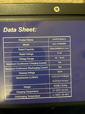
These are the specs of the batteries and I have 4 of them in parallel.

bat_specs.jpg
 
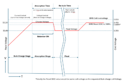
Andy from the Off-Grid-Garrage YouTube channel has done a *lot* of work on charge cycles and charge voltages. This is what he recommends:

Notice that the cell overvoltage is well above the charge voltage target. During changing this allows a cell to go above the target without triggering a cell overvoltage.1707323938117.png

The interesting thing is that he does not turn on balance till the first cell hits the target voltage. He also leaves the charger on for a while to give the balancer time to do its thing. (The Absorption stage should be called the 'balance stage' for LiFePO4) Note: He has pretty much concluded that active balancers with a reasonably high balance current is needed. However, I suspect that if the absorption time is long enough a low current passive balancer could also work.
 
Back
Top