diy solar

diy solar

JK-BMS-CAN with new Cut-Off Charging Logic (open-source)

And changing 3 things at the same time makes it also difficult to figure out what's working, why, and why not. I'm also guilty of this sometimes ...

Change 1 thing at the time. Fully charge. Let it rest up there. See how it works in 1-2 days time. Then we see what to change and how.
Affirmative.....
 
You are not using the same version of the code on both of your ESP32 devices.
Please, slow down and properly think everything through.

The YAML you are using on your second ESP32 is more up to date than the other. I would suggest standardising on that.

I am concerned that you're changing settings far too often to truly understand the impact and results. This won't work in the long run.

Go back to basics, correctly balance and fully charge each battery pack.
OOOOH My days....slow down for sure...
all this time i did not notice this..lol
damn
 
Current state - lets see if it stops at 10% , if it does i leave it like that, i like that the second battery discharges to lower depth that the master
View attachment 200866
Again, remember that your inverter stopping at 10% SOC depends on the JK BMS properly calculating that SOC in the first place.

If BMS thinks SOC is 20% but you're hitting UVP, then you most likely have a wrong SOC value being reported (because of no calibration) ...

And it will only get worse over time. The only solution is to let them equalize at the higher end of the voltage curve for a few hours each day/week.
got it....
 
OK but please recharge it fully and let it rest high up there for a while until SOC resets to "real" 100%. Otherwise it will not work in the future as I said before :) .
o.k i will start recharge sooner than originally set bcos i don't want to lose sleep watching this again today lol...as i have never had both recharge fully to 100% i want to keep an eye on it.
@DrPablo

i am as we speak updating the Yaml to meet the same version
 
o.k i will start recharge sooner than originally set bcos i don't want to lose sleep watching this again today lol...as i have never had both recharge fully to 100% i want to keep an eye on it.
@DrPablo

i am as we speak updating the Yaml to meet the same version
I made the same mistake, that's why I'm telling you :) .
 
You are not using the same version of the code on both of your ESP32 devices.
Please, slow down and properly think everything through.

The YAML you are using on your second ESP32 is more up to date than the other. I would suggest standardising on that.

I am concerned that you're changing settings far too often to truly understand the impact and results. This won't work in the long run.

Go back to basics, correctly balance and fully charge each battery pack.
Why is Absorption time removed?
 
after upgrading to the latest as with Batt-2 , now it started charging then just stopped...not sure what parameter stopped it - just comparing values with the old code that was on it now

# Edit
Went downstairs to Find the 100a fuse tripped
not sure whats wrong , i am keeping an eye on it
 
Last edited:
Continuing with the "LEGO" approach, I've upgraded from the M5Stack Atom S3 Lite to the version featuring a small yet brilliant 0.85" TFT display.

Now, the ESP32 Atom S3 not only handles protocol conversion (I opted for the BLE version for enhanced hardware simplicity), but also serves as a real-time monitor. It displays:

  • Top bar: BLE and CAN status
  • Bottom bar: Charging status
  • Center: Basic information such as State of Charge (SoC), Voltage, Current, etc., with paging enabled via the push button.
YAML file off course available
enjoy !

that is really cool...
 
Continuing with the "LEGO" approach, I've upgraded from the M5Stack Atom S3 Lite to the version featuring a small yet brilliant 0.85" TFT display.

Now, the ESP32 Atom S3 not only handles protocol conversion (I opted for the BLE version for enhanced hardware simplicity), but also serves as a real-time monitor. It displays:

  • Top bar: BLE and CAN status
  • Bottom bar: Charging status
  • Center: Basic information such as State of Charge (SoC), Voltage, Current, etc., with paging enabled via the push button.
YAML file off course available
enjoy !
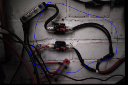
Wow. Ok. That’s money!!!
 
The circled wire is warm , not hot but warm -- yes i know i will order a higher grade wire and replace it, i improvised as you can see by doubling them up.

1709927909406.png

it's not hot but it's warm - is this o.k for the now? - what do you guys think?

regards
 
but i don't understand why the 100a flipped when the combined max amperage is 40a

and i have set in the config restricted to 40 amp per BMS.
 
Continuing with the "LEGO" approach, I've upgraded from the M5Stack Atom S3 Lite to the version featuring a small yet brilliant 0.85" TFT display.

Now, the ESP32 Atom S3 not only handles protocol conversion (I opted for the BLE version for enhanced hardware simplicity), but also serves as a real-time monitor. It displays:

  • Top bar: BLE and CAN status
  • Bottom bar: Charging status
  • Center: Basic information such as State of Charge (SoC), Voltage, Current, etc., with paging enabled via the push button.
YAML file off course available
enjoy !
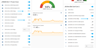
Did you definitely combine Wire and BLE?

Which code did you use as there is no section for MAC in the wire version
 
but i don't understand why the 100a flipped when the combined max amperage is 40a

and i have set in the config restricted to 40 amp per BMS.
I think it's time for a schematic with number, size of wires, etc. Anything else will be pure guessing on our part.

Put something down using draw.io / diagrams dot net or similar.

If they are warm almost hot I'd say you need to be careful. Maybe not tightened correctly, lack of cleaning of contact points, incorrect crimping, many things, Alu to copper connection, ...

What flipped? When? Between what and what? Remember that the currents you need to consider are all of them... And while I inverter = ibat1 + ibat2 = defined, during transients (like bms ovp in my case and ovpr later), you can get pretty huge spikes in the individual currents like I inverter = 100A = 150A + (-50A)
 
Did you definitely combine Wire and BLE?

Which code did you use as there is no section for MAC in the wire version
NO I keep separate the two versions as per @Sleeper85 project approach
I just add the online monitor display extra code on the BLE version but could be easily replicated/ported on the wired version
 
what would stop all this from discharging now - since i started using the new codes i have not been finding it easy
i struggle to get it to charge beyond 80% and now its not discharging just a trickle...
1710003843071.png
 
Back
Top