diy solar

diy solar

JK-BMS-CAN with new Cut-Off Charging Logic (open-source)

I do all my updates OTA - think the initial flashing should be done via USB
there might be a way to do thith OTA as well using a fixed IP, but i would not recommend it, cause OTA the bootloader and partitions doesnt get flashed - so initial OTA can caus problems.

you have to use the last will topic on the slave ESPs - so the broker notifies if the node is not connected anymore
i have also implemented a binary sensor on my slaves which states the BLE connection
Both conditions must be met to be a valid source for the master - otherwise the node gets ignored then.
the inverter will be told a charge and discharge current of 0A and a charge voltage of 0V
In my deye i have to enable "BMS_err_stop" to get the inverter to shut off - otherwise the CAN Data gets ignored and the inveter still works (charging, discharging, load etc)
There need to be done further investigation
last will topic on the slave ESPs?

How to enable that parameter on the Deye? Via canbus?

I always did usb flashing on the syssi code, never figured out (or tried so far) a way to do OTA on esphome (although I saw an OTA password) . I think it's easier on tasmota for that...
 
last will topic on the slave ESPs?
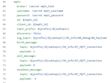
this can be found in the mqtt section for reference

1710506258103.png

How to enable that parameter on the Deye? Via canbus?
the option is under advanced functions in the deye inverter menue

I always did usb flashing on the syssi code, never figured out (or tried so far) a way to do OTA on esphome (although I saw an OTA password) . I think it's easier on tasmota for that...
OTA is really easy - and its already included in my repo - you just have to set a OTA password in your secrets.yaml if you already havent.

ota_password: "xxxxxxxxxxxxxxxxxxxxxxxxxxxxxxxxxxxx"

i really need to get my JK-Repo to be done...
seems that there are more of things to consider as i had in mind :eek:
 
this can be found in the mqtt section for reference

View attachment 202204


the option is under advanced functions in the deye inverter menue


OTA is really easy - and its already included in my repo - you just have to set a OTA password in your secrets.yaml if you already havent.

ota_password: "xxxxxxxxxxxxxxxxxxxxxxxxxxxxxxxxxxxx"

i really need to get my JK-Repo to be done...
seems that there are more of things to consider as i had in mind :eek:
But do you mean on the slave ESP32 mqtt section ? Or in your code ? I assume each JK BMS syssi ESP32 has to send its birth/will message so that the master knows about its status. Just making sure I understand correctly :).

JK-Repo :unsure:? What are you planning ?
 
But do you mean on the slave ESP32 mqtt section ? Or in your code ? I assume each JK BMS syssi ESP32 has to send its birth/will message so that the master knows about its status. Just making sure I understand correctly :).

JK-Repo :unsure:? What are you planning ?
Yes you got me right - every slave needs to have that last will topic so the master can recognise if its available or not

I want to share my personal fork of syssi´s repo which is fully configured to work perfect with iobroker.
So all the topicsv of the slaves are in a certan order / structure....i was not happy with the default mqtt structure of esphome like /sensor/name/state

mine look like this:
1710508766490.png
 
Yes you got me right - every slave needs to have that last will topic so the master can recognise if its available or not

I want to share my personal fork of syssi´s repo which is fully configured to work perfect with iobroker.
So all the topicsv of the slaves are in a certan order / structure....i was not happy with the default mqtt structure of esphome like /sensor/name/state

mine look like this:
View attachment 202206
Maybe I can hold on for your code there then before deploying the system. L stay in voltage mode a bit longer then I guess.

EDIT: Do you think a "maintenance switch" in case you put a battery offline for maintenance would be a good idea ? Basically one maintenance switch for each BMS, then you ignore if that BMS is offline etc ?
 
Last edited:
Good to hear you found and resolved an issue, are your cables also rated for 100A?
The actual battery wire looks like a 8wg - and this is max 55 @ 90 degrees c

so I think i would have to install my 40 amp fuses instead - thanks for pointing that out.
 
The actual battery wire looks like a 8wg - and this is max 55 @ 90 degrees c

so I think i would have to install my 40 amp fuses instead - thanks for pointing that out.
Be careful on the fuse power dissipation (depending on fuse type) and the power capability of your fuse holder/socket.

You might protect the cable but melt the fuse holder etc. Particularly with aR/gS (fast or semiconductor fuses).
 
Be careful on the fuse power dissipation (depending on fuse type) and the power capability of your fuse holder/socket.

You might protect the cable but melt the fuse holder etc. Particularly with aR/gS (fast or semiconductor fuses).
What Amp fuse do you recommend for 8 gauge wire.
the system cable was a 2kw inverter spec. 4.8 kw Batt capacity....it didn't have a fuse before, i just installed a fuse for extra safety ....
 
Weird issue today with this project v 1.17.3 and my M5stack setup. It simply stopped working and stopped reporting to HA. When I plug it into my Mac usb reprogram it using same code/config, it works perfectly fine, controls inverter and reports to HA.

I let it run for a bit to confirm all good, disconnect from MacBook and plug into usb power adapter, nothing works (yes the power adapter and cable is perfectly fine). I the plug usbC into Mac and still nothing. I reflash and all works again.

Seems it only works directly after flashing.

UPDATE: Seems I was a little impatient, seems to take about 15 minutes for it to start working and sending CAN message to inverter. I don't recall it taking this long before.
 
Last edited:
What Amp fuse do you recommend for 8 gauge wire.
the system cable was a 2kw inverter spec. 4.8 kw Batt capacity....it didn't have a fuse before, i just installed a fuse for extra safety ....
AWG 8 is quite small.

I'm used to work in metric, NOT in imperial.

For this kind of sizing, I usually refer to the great Legrand Power Book 04 - Sizing conductors and selecting protection devices (it's quite old from 2009):

Cable current capacity depends on:
- Type of Insulation (PVC: 70°C, XLPE: typically 90°C, Silicone: see Manufacturer Information, EPR: Depends - some are 60°C [H07RN-F] -
some are 70°C - some are 80°C [NSGAFOU Cable in Germany for Instance])
- Installation Method (under thermal insulation: A, in conduit on a wooden wall: B, on a wooden wall: C, D: in the ground, E/F: in free air). If you want to be conservative you can choose B1/B2. If you want to be more realistic then C might be a good option.
- How many cables / wires you have in parallel (group of circuits)
- Ambient temperature

Assuming pretty much standard ambient temperature and only PVC2 / PR2 (you don't have 4 wires in parallel all fully loaded etc) you are somewhere in this region depending if PVC or XLPE 90°C:

1710653935581.png


With this in mind, for a *Breaker* I'd select 40A Rating.

However, for a fuse, please refer to the great ABB guideline

Also from Schneider Electrical Installation Wiki:

1710654267523.png

1710654282301.png

1710654292374.png
1710654300063.png


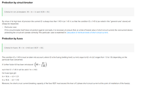
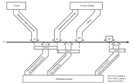
Applying Condition (1):
(1) Ib (your circuit current) <= In (rating of breaker or fuse) <= Iz (carrying capacity of the cable ~ 40-46 A from the table above)

Note that
By virtue of its high level of precision the current I2 is always less than 1.45 In (or 1.45 Ir) so that the condition I2 ≤ 1.45 Iz (as noted in the “general rules” above) will always be respected.
Now, for a fuse you need to check that condition as well !
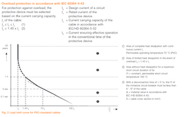
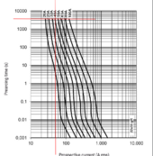
(2) Fuse Current vs Tripping Time Characteristic must satisfy
I2 <= 1.45 x Iz = 1.45 x 40A = 58 A

I take for instance a gR type fuse


Now - PLEASE CORRECT ME IF I'M WRONG HERE - The I2 Current corresponds to 1h duration (according to ABB document)
1710654871877.png


So a 40A gR fuse is on the edge for the second condition but still satisfies it [50A < 58A] (but you can argue that the cable Iz is probably higher than 40A that I very conservatively stated).


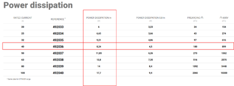
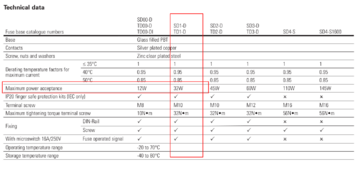
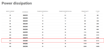
Last but not least check the power dissipation vs your fuse holder / base
1710655039975.png

Example of fuse holder:

1710655091377.png

Note that a gR fuse is NOT very fast. If we talk about fuse speed (from FASTEST to SLOWEST): aR < gS < gR < gG

So it mostly depends what TYPE of fuse you select.
Then you will have a range of SIZE (NH0, NH1, NH2 blade fuses, 10x38 mm, 22x58 mm, ...) fuses.

My protection scheme is based on:
- JK BMS (200A)
- 315A aR Fuse (https://www.tme.eu/dk/en/details/365280/nh-fuses/df-electric/) in NH1 Fuse Base (https://www.omnical.co/products/eaton/sd1-d/2262274 + https://www.omnical.co/products/eaton/sd12-sk/2262273)
- 100 A Characteristic B Circuit Breaker (Schneider C120H)

And for the Specifics in my case:


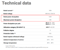
1710655357872.png


1710655432908.png

Now Power dissipation scaling of Pn x (Ioperation / Irated)^2 does NOT really work that well with fuses. The reason is simply that the resistance variation versus temperature is significant. Already if you just consider an Aluminium or Copper conductor, at 300°C you have DOUBLE the resistance / losses than at 20°C ! Fuses might be even more.
Nevertheless, you are being conservative with Pn x (Ioperation / Irated)^2 - If you try Pn x 0.8^2 = 49W while the table states 43W ...
So for me very conservatively:

P100 = 77 W x (100A / 315A)^2 = 7.76W

But of course it's also OVERSIZED on PURPOSE for other reasons (e.g. Power/Thermal Cycling, avoid tripping on Inrush, etc).

EDIT 1: and of course if you are based in US / using UL-CSA components, you probably should refer to a UL standard, which I'm NOT very familiar with

EDIT 2: if you select an aR fuse, you will have NO OVERLOAD PROTECTION AT ALL (only short-circuit protection). And if you *try* to overload an aR fuse, it will behave like a bomb and explode/disintegrate in a non-normal way (I have seen pictures of this type of fuses with a bullet-like hole in it as well ...)

EDIT 3: of course you need to make sure that your fuse is suitable for DC usage (most are AC !)
 
Last edited:
AWG 8 is quite small.

I'm used to work in metric, NOT in imperial.

For this kind of sizing, I usually refer to the great Legrand Power Book 04 - Sizing conductors and selecting protection devices (it's quite old from 2009):

Cable current capacity depends on:
- Type of Insulation (PVC: 70°C, XLPE: typically 90°C, Silicone: see Manufacturer Information, EPR: Depends - some are 60°C [H07RN-F] -
some are 70°C - some are 80°C [NSGAFOU Cable in Germany for Instance])
- Installation Method (under thermal insulation: A, in conduit on a wooden wall: B, on a wooden wall: C, D: in the ground, E/F: in free air). If you want to be conservative you can choose B1/B2. If you want to be more realistic then C might be a good option.
- How many cables / wires you have in parallel (group of circuits)
- Ambient temperature

Assuming pretty much standard ambient temperature and only PVC2 / PR2 (you don't have 4 wires in parallel all fully loaded etc) you are somewhere in this region depending if PVC or XLPE 90°C:

View attachment 202606


With this in mind, for a *Breaker* I'd select 40A Rating.

However, for a fuse, please refer to the great ABB guideline

Also from Schneider Electrical Installation Wiki:

View attachment 202608

View attachment 202609

View attachment 202610
View attachment 202611


Applying Condition (1):
(1) Ib (your circuit current) <= In (rating of breaker or fuse) <= Iz (carrying capacity of the cable ~ 40-46 A from the table above)

Note that
By virtue of its high level of precision the current I2 is always less than 1.45 In (or 1.45 Ir) so that the condition I2 ≤ 1.45 Iz (as noted in the “general rules” above) will always be respected.
Now, for a fuse you need to check that condition as well !
(2) Fuse Current vs Tripping Time Characteristic must satisfy
I2 <= 1.45 x Iz = 1.45 x 40A = 58 A

I take for instance a gR type fuse


Now - PLEASE CORRECT ME IF I'M WRONG HERE - The I2 Current corresponds to 1h duration (according to ABB document)
View attachment 202613


So a 40A gR fuse is on the edge for the second condition but still satisfies it [50A < 58A] (but you can argue that the cable Iz is probably higher than 40A that I very conservatively stated).


Last but not least check the power dissipation vs your fuse holder / base
View attachment 202614

Example of fuse holder:

View attachment 202615

Note that a gR fuse is NOT very fast. If we talk about fuse speed (from FASTEST to SLOWEST): aR < gS < gR < gG

So it mostly depends what TYPE of fuse you select.
Then you will have a range of SIZE (NH0, NH1, NH2 blade fuses, 10x38 mm, 22x58 mm, ...) fuses.

My protection scheme is based on:
- JK BMS (200A)
- 315A aR Fuse (https://www.tme.eu/dk/en/details/365280/nh-fuses/df-electric/) in NH1 Fuse Base (https://www.omnical.co/products/eaton/sd1-d/2262274 + https://www.omnical.co/products/eaton/sd12-sk/2262273)
- 100 A Characteristic B Circuit Breaker (Schneider C120H)

And for the Specifics in my case:


View attachment 202617


View attachment 202618

Now Power dissipation scaling of Pn x (Ioperation / Irated)^2 does NOT really work that well with fuses. The reason is simply that the resistance variation versus temperature is significant. Already if you just consider an Aluminium or Copper conductor, at 300°C you have DOUBLE the resistance / losses than at 20°C ! Fuses might be even more.
Nevertheless, you are being conservative with Pn x (Ioperation / Irated)^2 - If you try Pn x 0.8^2 = 49W while the table states 43W ...
So for me very conservatively:

P100 = 77 W x (100A / 315A)^2 = 7.76W

But of course it's also OVERSIZED on PURPOSE for other reasons (e.g. Power/Thermal Cycling, avoid tripping on Inrush, etc).

EDIT 1: and of course if you are based in US / using UL-CSA components, you probably should refer to a UL standard, which I'm NOT very familiar with

EDIT 2: if you select an aR fuse, you will have NO OVERLOAD PROTECTION AT ALL (only short-circuit protection). And if you *try* to overload an aR fuse, it will behave like a bomb and explode/disintegrate in a non-normal way (I have seen pictures of this type of fuses with a bullet-like hole in it as well ...)

EDIT 3: of course you need to make sure that your fuse is suitable for DC usage (most are AC !)
Gadem!! that a lot of maths- what are u are professor or something?
 
Gadem!! that a lot of maths- what are u are professor or something?
Just electrical engineer.

The devil is in the detail as usual :ROFLMAO:.

And I cannot do the work for you. You did not provide a schematic or part number so I have no clue what TYPE or SIZE of fuse you are using :confused: . You have to look that up yourself ...
 
UPDATE: Seems I was a little impatient, seems to take about 15 minutes for it to start working and sending CAN message to inverter. I don't recall it taking this long before.

No, it's not normal for it to take so long. An ESP32 starts very quickly and should be working after 1 minute. The CAN connection may not start directly, after sending 20 CAN IDs without response from the inverter the CAN connection is paused for 2 minutes before trying to connect again. You can increase this number from 20 to 30 to test if it works better for you.
 
V1.17.4 has been released on GitHub:

Changelog:
- Added "SMA" to CAN BMS names
- Added function "Auto Charge Voltage Control" to avoid OVP alarms and improve balancing
- Categorised sensors
- Set time source to SNTP
- Min battery voltage based on BMS value
- Added "Last Complete Charge" timestamp
- Renamed daily energy sensors
- Added input number display option (slider or box)

The main feature added to this release is 'Auto Charge Voltage Control'.
When enabled, the requested charge voltage will automatically reduce as cell voltage delta increases - this reduces the chance of cell overvoltage as well as providing more time for cell balancing to occur.
This feature will only be active if cell voltage delta is greater than 5mv (and if 'CAN Automatic Charge Voltage' is enabled).
Thanks go to Matthias U and Stuart Pittaway, creators of the original logic (found here).

For those interested, this logic calculates how much additional voltage is required for the max voltage cell to reach target. It will also compare all other cells, applying a weighting factor that should prevent any cell from exceeding target voltage.
The logic is not easy to grasp, so a helper spreadsheet is available here for scenario testing.

Final note, for any users using this code with a Solis inverter, I recommend setting the CAN protocol and CAN BMS name to 'SMA', then setting the battery name to 'AoBo' on the inverter itself.
This resolves an issue with the Solis implementation of Pylontech control, resulting in more accurate voltage regulation.
I'm looking very forward for @Der_Hannes implementation of this. Is there something I could do to help ? I'm really an ESPHome NOOB though :fp

@Der_Hannes : can you confirm that only CAN_H and CAN_L are needed on the inverter side ? Usually also CAN_GND is exposed on a CAN interface (I would suppose it should be tied to GND in this case, but maybe it's intentionally left floating to prevent a ground loop ?).
1710829252835.png
 
I'm looking very forward for @Der_Hannes implementation of this. Is there something I could do to help ? I'm really an ESPHome NOOB though :fp

@Der_Hannes : can you confirm that only CAN_H and CAN_L are needed on the inverter side ? Usually also CAN_GND is exposed on a CAN interface (I would suppose it should be tied to GND in this case, but maybe it's intentionally left floating to prevent a ground loop ?).
View attachment 202971
MultiBMS support is on the list for development in the next version, which @Der_Hannes has been involved with.
@Sleeper85 has been working on reconfiguring the code so it's more modular, making it possible to 'plug in' different functions like displays, multiBMS, etc.
 
MultiBMS support is on the list for development in the next version, which @Der_Hannes has been involved with.
@Sleeper85 has been working on reconfiguring the code so it's more modular, making it possible to 'plug in' different functions like displays, multiBMS, etc.
Aaah so it's not a separate project, what @Der_Hannes is working on? So the plan is indeed to use mqtt as the "final" solution?

When is the new version scheduled to be released though? I was aiming for last weekend now more realistically one day this week to implement communication with inverter... I am having enough of these OVP events and BMS tripping all the time (although at like 10-20A charge it should not do much damage I believe)
 
There's no timeline for release at this point, it's still very, very early days and multiBMS support is still in planning stages.

For me personally, multi BMS support will need to be reliable and capable of running without WiFi, etc, so that might make a MQTT method unfeasible.
Once we get to testing, you could probably get involved.
 
If you have one particular pack that is misbehaving, perhaps set up this project on that pack only.
You will get better control than you already have, and the code should prevent OVP alarms.
The second pack might be 'dumb' but it'd still see the same controlled voltage and current from the inverter.
That might also be a valid approach after all. I didn't hit OVP on battery 1 except in the very early days several months ago, when battery 2 was not even started.

I regularly hit OVP on battery 2 (cell 11 IIRC) 3-5 times a day
 
Back
Top