diy solar

diy solar

JK-BMS-CAN with new Cut-Off Charging Logic (open-source)

I have never ever managed to keep an ESPhome device connected to my network for longer than a couple of minutes. I don't know what the hell I'm doing wrong but apparently everyone else is doing it wrong too.
If you specify the EXACT device we might be able to try to help ...

One one side, power supply, cabling (microUSB/USB-C connector or directly onto some pins) and quality of the board (and its components) are EXTREMELY important.

On the other side, you have your network, the network configuration, the network environment (EMC/EMI), gain of antennas and the likes.
Having both 2.4GHz and 5.0GHz can also cause issues. Suggest you turn 5.0GHz band OFF. And select a non-overlapping (and hopefully without other neighbor APs using it) 2.4GHz channel (1,6,11).

I just faced a lot of network troubleshooting due to OTA not working. Incredibly, everything else was quite happy to work.
The first step into the solution for me was to setup Static Routes correctly. It's still NOT working, but I already narrowed down extremely the field of possibilities. And iperf3 finally shows some decent speed.

Another potential issue is your YAML device configuration. That can include issues such as stack size, memory / flashing settings and the likes.
 
This the old one I am using the project on
 

Attachments

  • Screenshot_20240407-193831.png
    Screenshot_20240407-193831.png
    208.7 KB · Views: 13
- Please CONFIRM the SKU part number of the M5Stack Controller (Atom S3 Lite) and especially the CANbus Isolated Adapter (one is UNIT the other is BASE). I was using the wrong one (UNIT/Base confusion, availability at suppliers, ...) so the GPIO pinout was wrong.

- Did you try reversing CAN_TX and CAN_RX ? Did you try reversing the GPIO pins on the ESP32 side in the config ?

- Did you try pin 2+3 or 6+7 ? Depending on how you look at the RJ45 Plug (from front or from back ? with "locking tab" facing up or down ? etc) or RJ45 Socket (from front or from back ? with space for the "locking tab" facing up or down ? etc) it can be different. And of course there are plenty of "opportunities" to switch everything around. I was VERY methodical for the RS485 Inverter Communication (NOT the CANbus where I got the pinout wrong ...), but it's VERY easy to get it backwards ...

This is for my Deye Modbus Port:
View attachment 207631

While the BMS (the one you are trying to use) is:

View attachment 207632

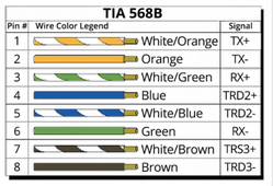
- Are you sure you are NOT making a Crossover cable by mixing TIA 568A and TIA 568B ?
View attachment 207633

- Did you add the Termination Resistor (120 Ohm) ?

- To check the basic communication if you are on GNU/Linux with some CANbus adapter lying around you could try "cansniff" command part of the "can-utils" package.

That's what I tried here: https://diysolarforum.com/threads/j...-logic-open-source.79325/page-37#post-1046211

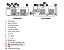
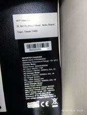
EDIT 1: on your inverter I can see this at https://www.mppsolar.com/manual/PIP-GEW/3024_5048GEW manual-20230919.pdf
View attachment 207636

So the proper pins if you look at the RJ45 Plug with the locking tab facing DOWN (!!) are the pins on the RIGHT side.
Look at my Deye screenshot for more information (you need to turn the RJ45 Plug 180° to match the RJ45 socket, then the Pin 7+8 of the RJ45 Plug are on the right side [when the RJ45 locking tab is facing DOWN], just like the RJ45 Socket).
"- Please CONFIRM the SKU part number of the M5Stack Controller (Atom S3 Lite) and especially the CANbus Isolated Adapter (one is UNIT the other is BASE). I was using the wrong one (UNIT/Base confusion, availability at suppliers, ...) so the GPIO pinout was wrong."

AtomS3 Lite ESP32S3 Dev Kit.
SKU: C124

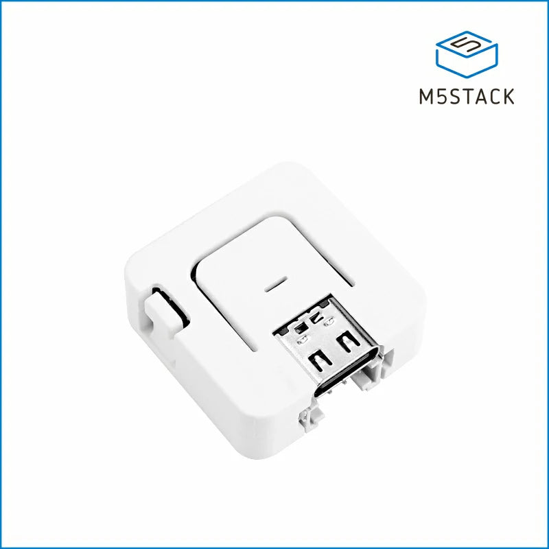
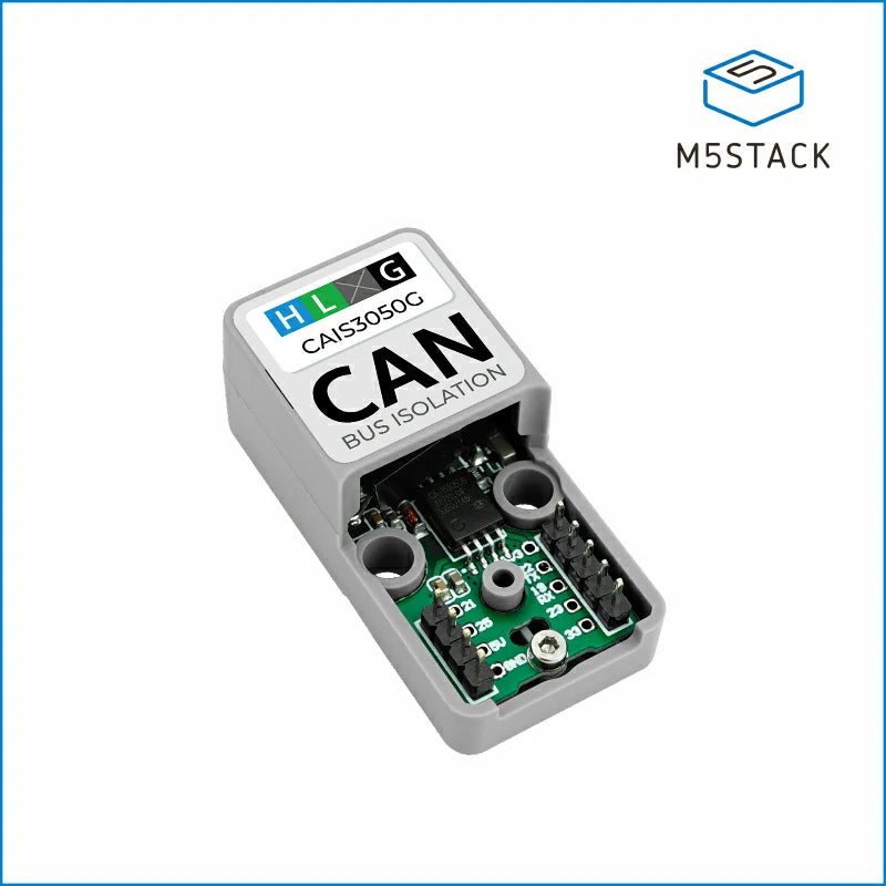
ATOMIC CANBus Base (CA-IS3050G)
SKU: A103

"- Did you try reversing CAN_TX and CAN_RX ? Did you try reversing the GPIO pins on the ESP32 side in the config ?"
ESP32 yaml:
# GPIO pins your CAN bus transceiver
# Using ATOMIC CANBus Base (CA-IS3050G) - SKU: A103
can_tx_pin: GPIO5
can_rx_pin: GPIO6

"- Did you try pin 2+3 or 6+7 ? Depending on how you look at the RJ45 Plug (from front or from back ? with "locking tab" facing up or down ? etc) or RJ45 Socket (from front or from back ? with space for the "locking tab" facing up or down ? etc) it can be different. And of course there are plenty of "opportunities" to switch everything around. I was VERY methodical for the RS485 Inverter Communication (NOT the CANbus where I got the pinout wrong ...), but it's VERY easy to get it backwards ..."

Default connection:
ATOM SKU: A103: CAN-High ---> pin 6 BMS Port inverter
ATOM SKU: A103: CAN-Low ---> pin 7 BMS Port inverter

Reverse connection:
ATOM SKU: A103: CAN-High ---> pin 7 BMS Port inverter
ATOM SKU: A103: CAN-Low ---> pin 6 BMS Port inverter

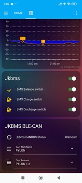
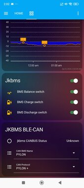
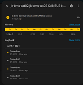
But still not connected and CAN Bus status unknown.
Sorry my english is very bad.
 

Attachments

  • 1715107751-IMG_20240408_014800.jpg
    1715107751-IMG_20240408_014800.jpg
    94.3 KB · Views: 7
  • Screenshot_2024-04-08-02-02-28-840_io.homeassistant.companion.android.jpg
    Screenshot_2024-04-08-02-02-28-840_io.homeassistant.companion.android.jpg
    66.7 KB · Views: 7
  • Screenshot_2024-04-08-02-02-19-481_io.homeassistant.companion.android.jpg
    Screenshot_2024-04-08-02-02-19-481_io.homeassistant.companion.android.jpg
    66.5 KB · Views: 7
"- Please CONFIRM the SKU part number of the M5Stack Controller (Atom S3 Lite) and especially the CANbus Isolated Adapter (one is UNIT the other is BASE). I was using the wrong one (UNIT/Base confusion, availability at suppliers, ...) so the GPIO pinout was wrong."

AtomS3 Lite ESP32S3 Dev Kit.
SKU: C124

ATOMIC CANBus Base (CA-IS3050G)
SKU: A103

"- Did you try reversing CAN_TX and CAN_RX ? Did you try reversing the GPIO pins on the ESP32 side in the config ?"
ESP32 yaml:
# GPIO pins your CAN bus transceiver
# Using ATOMIC CANBus Base (CA-IS3050G) - SKU: A103
can_tx_pin: GPIO5
can_rx_pin: GPIO6

"- Did you try pin 2+3 or 6+7 ? Depending on how you look at the RJ45 Plug (from front or from back ? with "locking tab" facing up or down ? etc) or RJ45 Socket (from front or from back ? with space for the "locking tab" facing up or down ? etc) it can be different. And of course there are plenty of "opportunities" to switch everything around. I was VERY methodical for the RS485 Inverter Communication (NOT the CANbus where I got the pinout wrong ...), but it's VERY easy to get it backwards ..."

Default connection:
ATOM SKU: A103: CAN-High ---> pin 6 BMS Port inverter
ATOM SKU: A103: CAN-Low ---> pin 7 BMS Port inverter

Reverse connection:
ATOM SKU: A103: CAN-High ---> pin 7 BMS Port inverter
ATOM SKU: A103: CAN-Low ---> pin 6 BMS Port inverter

But still not connected and CAN Bus status unknown.
Sorry my english is very bad.
SKU / Part numbers look good.

Did you make sure it's really pin 6+7 and not 2+3 (if you look at the RJ45 plug in the "opposite" way) ?

Did you set the correct configuration on your Inverter (on the Deye you can switch between CAN and RS485 for BMS communication depending on Battery Brand and Protocol). You also have the "dual use" port. Did you select "CAN" on the Inverter as communication Protocol for your BMS/Battery ?
 
According to the diagram you have attached, pin 6 is CANH and pin 7 is CANL. The picture is contacts side facing up towards the viewer.
these two wires should be connected to the module's CANH and CANL output pins respectively.
Also, I'm assuming you've already set the Inverter to the appropriate PYLONTECH battery mode.
View attachment 207637
I have set the PIP-5048GEW to PYLON mode.
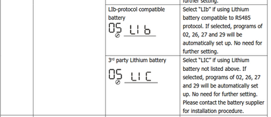
And also change to LIA, LIB, LIC, Weco, Soltaro.
After 3 minutes the inverter displays error code "61"
 
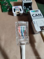
@Bram380 please a close-up picture of that RJ45 plug, both with the locking tab facing UP and the locking tab facing DOWN

I cannot see the wire colours.

Also, did you check if you crimped that RJ45 correctly ? Sometimes I also had connectors that would not transmit data [reliably] just due to bad crimping [tool].

EDIT 1: Did it EVER communicate with the Inverter or not at all ?

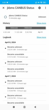
You can check that on Home Assistant if you added the ESPHome to it
1712520592042.png

1712520571162.png

(in my case it reported down for a few seconds I believe because I restarted the access point / DHCP Server / Docker Container)
 
Last edited:
@Bram380 please a close-up picture of that RJ45 plug, both with the locking tab facing UP and the locking tab facing DOWN

I cannot see the wire colours.

Also, did you check if you crimped that RJ45 correctly ? Sometimes I also had connectors that would not transmit data [reliably] just due to bad crimping [tool].

EDIT 1: Did it EVER communicate with the Inverter or not at all ?

You can check that on Home Assistant if you added the ESPHome to it
View attachment 207785

View attachment 207784

(in my case it reported down for a few seconds I believe because I restarted the access point / DHCP Server / Docker Container)
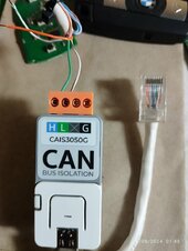
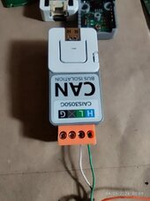
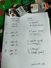
Here connection already tried:
 

Attachments

  • IMG_20240408_030656.jpg
    IMG_20240408_030656.jpg
    97.2 KB · Views: 7
  • IMG_20240408_030924.jpg
    IMG_20240408_030924.jpg
    88.6 KB · Views: 7
  • IMG_20240408_031540.jpg
    IMG_20240408_031540.jpg
    160.6 KB · Views: 7
Here connection already tried:
I am struggling to see the colors you have both on the RJ45 Plug and the CANBus Adapter to be honest ...

From what I can see pin 1&2 are white-orange and orange, so I assume you are following TIA 568B. Is this correct ?

This should be the pinout:
1712521405649.png

But I see from your description sheet that you already tried all combinations basically. Thanks for the schematic with description, that helps !

Did you add the termination resistor ?

Are you sure you are using the correct RJ45 port on the Inverter ? I ask because the Deye has like 4 or even 5 ... They are quite clearly labeled, but just to make sure :) .

1712521723556.png
 
You can always try but according to my readings the PYLON protocol on Voltronic inverters like MPP Solar only works on RS485 and not on CAN bus. On the other hand, the can bus should work for two other battery models with a protocol completely different from what we use (therefore not supported).
So MPPSolar PIP-5048GEW does not support CAN Bus.
And must use the RS485 protocol.
OK, where should I change the ESP32 yaml?
 

Attachments

  • jkbms_ble_can_atoms3_lite.rar
    13.7 KB · Views: 0
@Bram380 : also did you select "Lithium" as mode for your inverter ? It might be that BMS communication doesn't occur otherwise. The Deye seems to try to communicate with the BMS regardless.

But it's weird that you get an error if no communication would be expected ...
I would go with PYLON (PYL) to be honest but that's just my positive experience on the Deye :) .

1712522161471.png
1712522210639.png


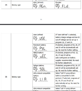
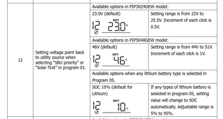
According with the manual however PYL option for 05 does NOT set option 12.
Did you adjust that correctly ?
1712522309205.png
 
I am struggling to see the colors you have both on the RJ45 Plug and the CANBus Adapter to be honest ...

From what I can see pin 1&2 are white-orange and orange, so I assume you are following TIA 568B. Is this correct ?

This should be the pinout:
View attachment 207793

But I see from your description sheet that you already tried all combinations basically. Thanks for the schematic with description, that helps !

Did you add the termination resistor ?

Are you sure you are using the correct RJ45 port on the Inverter ? I ask because the Deye has like 4 or even 5 ... They are quite clearly labeled, but just to make sure :) .

View attachment 207795
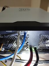
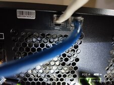
I use like this:
- White cable to BMS port (12) for JKBMS.
- Blue cable to RS232 port (11) for ESP32 Home Assistant.
 

Attachments

  • IMG_20240408_033747.jpg
    IMG_20240408_033747.jpg
    119.2 KB · Views: 3
  • IMG_20240408_033830.jpg
    IMG_20240408_033830.jpg
    338.9 KB · Views: 3
  • IMG_20240408_034027.jpg
    IMG_20240408_034027.jpg
    162.8 KB · Views: 3
I use like this:
- White cable to BMS port (12) for JKBMS.
- Blue cable to RS232 port (11) for ESP32 Home Assistant.
That looks correct.

But if it's like @Sleeper85 said it's not going to work on PYLON ...

Maybe LIA but it's not clear what it really is besides "CANbus" ...

1712524353589.png

You should really ask MPP Solar for some Battery Compatibility Guide to really know what the protocol is.
Deye has this for instance:
 
That looks correct.

But if it's like @Sleeper85 said it's not going to work on PYLON ...

Maybe LIA but it's not clear what it really is besides "CANbus" ...

View attachment 207808

You should really ask MPP Solar for some Battery Compatibility Guide to really know what the protocol is.
Deye has this for instance:
Already try LIA mode.
But JKBMS not connected.

Thank you for advice.
 
"- Please CONFIRM the SKU part number of the M5Stack Controller (Atom S3 Lite) and especially the CANbus Isolated Adapter (one is UNIT the other is BASE). I was using the wrong one (UNIT/Base confusion, availability at suppliers, ...) so the GPIO pinout was wrong."

AtomS3 Lite ESP32S3 Dev Kit.
SKU: C124

ATOMIC CANBus Base (CA-IS3050G)
SKU: A103

"- Did you try reversing CAN_TX and CAN_RX ? Did you try reversing the GPIO pins on the ESP32 side in the config ?"
ESP32 yaml:
# GPIO pins your CAN bus transceiver
# Using ATOMIC CANBus Base (CA-IS3050G) - SKU: A103
can_tx_pin: GPIO5
can_rx_pin: GPIO6

"- Did you try pin 2+3 or 6+7 ? Depending on how you look at the RJ45 Plug (from front or from back ? with "locking tab" facing up or down ? etc) or RJ45 Socket (from front or from back ? with space for the "locking tab" facing up or down ? etc) it can be different. And of course there are plenty of "opportunities" to switch everything around. I was VERY methodical for the RS485 Inverter Communication (NOT the CANbus where I got the pinout wrong ...), but it's VERY easy to get it backwards ..."

Default connection:
ATOM SKU: A103: CAN-High ---> pin 6 BMS Port inverter
ATOM SKU: A103: CAN-Low ---> pin 7 BMS Port inverter

Reverse connection:
ATOM SKU: A103: CAN-High ---> pin 7 BMS Port inverter
ATOM SKU: A103: CAN-Low ---> pin 6 BMS Port inverter

But still not connected and CAN Bus status unknown.
Sorry my english is very bad.
This is exactly what i have x2
also ordered the one with a screen.....i will focus on getting these to work when i get back from holiday.
 
Already try LIA mode.
But JKBMS not connected.

Thank you for advice.

Weco and Soltaro would be the only two types of battery using the CAN bus and the protocol is completely different.

If you want to modify the CAN bus part to adapt it to one of these protocols I can guide you on the procedure to follow.

Ditto if you prefer to try PYLON or LIB in RS485.

The new version in the development branch is modular.

 
Last edited:
This is exactly what i have x2
also ordered the one with a screen.....i will focus on getting these to work when i get back from holiday.
Well they are working for me now (minus the wrong SKU of the Rs485 adapter...).

I quickly tried OTA on a Raspberry Pi inside my home. That's also working. Next is try in the garage but I don't see why that should fail...

TLDR if somebody is having OTA updates issues that when triggered brick the device, causing the watchdog to continuo trigger and never reboot (as it should do when OTA fails), then it's a network issue.

Check your network routing, routes gateway. Test point to point using iperf3, ping/traceroute are NOT that accurate (because typically ping ICMP is allowed no matter what). Tcptraceroute is somewhat better but can also give false positives. Check that using iper3 you get 100-1000 Mbit/S.

Of course you cannot test the Esp32 like that. But at least all the way until the last step (AP - > ESP32).

My solution was to define static routes.
 
I use like this:
- White cable to BMS port (12) for JKBMS.
- Blue cable to RS232 port (11) for ESP32 Home Assistant.
I think, the cable coming from the ATOMIC CANBus module should go into the BMS port.

What have you connected to the ports 12 and 11, can you show us both ??
 
Back
Top