diy solar

diy solar

Growatt 5kW ES + Mid-Point Transformer explained but not AC input from grid

You can't isolate the grid neutral, and still be connected to the grid L1 and L2. The neutral is bonded to ground at the main panel. Without a neutral wire. The loads will use the ground wire for a return path.
I explain the issues here.

I've read your explanation from the link you provided, tell me if my situation is an exception. My Main panel box is actually an automatic transfer switch for a whole house generator, my main panel is there for a sub panel and so is does not have a neutral/ground bond. If I run a neutral from my panel (sub panel) to the auto transformer it would not be bonded to the ground. Would this be a safe install without using the relay you had to use? Thanks
 
I've read your explanation from the link you provided, tell me if my situation is an exception. My Main panel box is actually an automatic transfer switch for a whole house generator, my main panel is there for a sub panel and so is does not have a neutral/ground bond. If I run a neutral from my panel (sub panel) to the auto transformer it would not be bonded to the ground. Would this be a safe install without using the relay you had to use? Thanks
It depends.
Is your N/G bond in the transfer switch?
Does that transfer switch break the neutral, also?
Or is it a common neutral setup? (All neutrals always connected together)
 
It depends.
Is your N/G bond in the transfer switch?
Does that transfer switch break the neutral, also?
Or is it a common neutral setup? (All neutrals always connected together)
Neutral and ground are bonded in the transfer switch, which is considered the main panel. What we use as a main panel is considered a sub panel and sub panels are not bonded between ground and neutral. I don't understand what you mean by "break the neutral"
 
Neutral and ground are bonded in the transfer switch, which is considered the main panel. What we use as a main panel is considered a sub panel and sub panels are not bonded between ground and neutral. I don't understand what you mean by "break the neutral"
Break = switch.
Does the transfer switch, switch the neutral?
Or are all neutrals on a common bar?
 
IMG_0570.JPGIMG_0571.JPGBreak = switch.
Does the transfer switch, switch the neutral?
Or are all neutrals on a common bar?
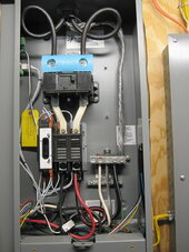
It does not switch the neutral, they are on a common bar. In the picture, the 3 coming from the bottom are neutral to the generator (white) then bare aluminum to ground bar in sub panel, then neutral to sub panel and from the top is neutral from grid. In the sub panel the ground bar and neutral bars are not bonded.
 
I don't see the N/G bond in the transfer switch. Please verify that it exists.
If it does, it provides the bond for everything.
If I run a neutral from my panel (sub panel) to the auto transformer it would not be bonded to the ground.
It would be bonded.
Would this be a safe install without using the relay you had to use?
It will be safe, as far as grounded.
But it will have the possibility of trying to balance the grid.
Do you know how many neighbors share your utility transformer?
 
I don't see the N/G bond in the transfer switch. Please verify that it exists.
If it does, it provides the bond for everything.

It would be bonded.

It will be safe, as far as grounded.
But it will have the possibility of trying to balance the grid.
Do you know how many neighbors share your utility transformer?
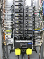
So as a retired plumber I don't know how some of the intricacies of electrical pathways are separated. If you look in the sub panel, you can see that the ground and neutral bus bars are separate. However, in the switch box, the ground for the sub panel is on the neutral bar. So there is a path for the sub panel ground bus to the neutral bus in the main panel box. So instead of using the neutral from the auto transformer, I used a neutral from the sub panel into the inverter panel box, and if one side of the AT failed, it would try and complete the circuit by flowing back to the sub panel via neutral, that goes back to the switch box which has a ground for the sub panel. But it is a dead end to ground, isn't it? The grounds from the sub panel can get to neutral, but the neutral from the sub panel cannot get to ground because it goes back to the neutral bus. it's just a circular flow. since the neutral can't get to ground, nothing should get energized that shouldn't if the AT fails. But that is only one scenario, there may be more potential dangers I'm not aware of. But the bottom line, at least as I understood the issue is that the neutral from the sub panel box has no path to ground because in the main/switch box, the neutral and ground bus bars are separate. Sorry for being so long winded but I kind of half think it out as I write. Plus I'm a plumber so what do I know about electricity.
 
So as a retired plumber I don't know how some of the intricacies of electrical pathways are separated. If you look in the sub panel, you can see that the ground and neutral bus bars are separate. However, in the switch box, the ground for the sub panel is on the neutral bar. So there is a path for the sub panel ground bus to the neutral bus in the main panel box. So instead of using the neutral from the auto transformer, I used a neutral from the sub panel into the inverter panel box, and if one side of the AT failed, it would try and complete the circuit by flowing back to the sub panel via neutral, that goes back to the switch box which has a ground for the sub panel. But it is a dead end to ground, isn't it? The grounds from the sub panel can get to neutral, but the neutral from the sub panel cannot get to ground because it goes back to the neutral bus. it's just a circular flow. since the neutral can't get to ground, nothing should get energized that shouldn't if the AT fails. But that is only one scenario, there may be more potential dangers I'm not aware of. But the bottom line, at least as I understood the issue is that the neutral from the sub panel box has no path to ground because in the main/switch box, the neutral and ground bus bars are separate. Sorry for being so long winded but I kind of half think it out as I write. Plus I'm a plumber so what do I know about electricity.
The purpose of the grounding system is to provide a low impedance (resistance) path for fault current, back to the source. (Through the N/G bond) So that a breaker or fuse can clear the fault, before anyone gets hurt.

In the transfer switch, I don't see any connection between the neutral bar and the ground bar, or enclosure. (There should be)

The only other issue is if you share your utility transformer with anyone else.
Well I don't know what you mean by share my utility transformer so I don't how to answer that. But let's just say there is a ground/neutral bond, if there is not I will call the Sparky that did the install and see what they say. Then, using a neutral from the sub panel would not solve the problem with the AT failing. I'll have to go back and re-read your other post in reference to the relay switch.
 
Last edited:
Back
Top