diy solar

diy solar

Which cables do I need for solar panels?

doox00

New Member
Joined
Jul 22, 2023
Messages
90
Location
US-MI
I am having a contractor install 20 panels on the roof of my pole barn, they are Talesun TP7G54M 400 watt (up to 500 watt) bifacial panels purchased from signaturesolar. I will have 2 rows of 10 panels each, each row wired in series, so two strings of 10 panels in each. The data sheet says the connectors are T01/LJQ-3-CSY/MC4/MC4-EVO2. I am new to solar panels and not sure if most panels use the same connector or not. But want to be sure to order the correct cables to make the connections as he installs the panels.

Thanks!
 
375 volts, panels are ~4000 watts per string.
4000W / 375V = 10.66A

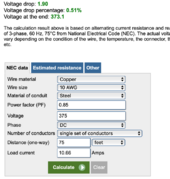
This says 10Awg copper (standard solar wire) is plenty:

Screen Shot 2024-04-13 at 12.25.05 PM.png
 
4000W / 375V = 10.66A

This says 10Awg copper (standard solar wire) is plenty:

View attachment 209183

So will one panel plug into the other in series with what is already on the panel or do I need jumper cables with the proper ends to make each connection from one panel to the other?
 
So will one panel plug into the other in series with what is already on the panel or do I need jumper cables with the proper ends to make each connection from one panel to the other?

The panels will plug one into another (your contractor should know how to go + to -)
after the series string is completed you'll need solar cable with the correct connector to go to a charge connector

the MC4 and the MC4-EVO-2 are both manufactured by Staubli and the manufacturer states they are of the same type (MC4) and compatible for connection, the requirements of the clause (same type from same manufacturer) are met when mating these plug connectors

While MC4 connectors are often referred to as computable, mixing brands often lead to problems
Case in point, I used Bourge MC4s on unknown MC4s from my panels. A year later the connections were corroded
I cut them all off and replaced with the same brand, 3 years later and no problem although I'll check again soon
 
So will one panel plug into the other in series with what is already on the panel or do I need jumper cables with the proper ends to make each connection from one panel to the other?
It depends on how long the wires are that were spec'd with the panels, and what the orientation of the panels is.


+10000 on making sure it's a compatible brand of MC4. Get them from Titan Connector or some real mail order supply house like that, not Amazon.

T01/LJQ-3-CSY/MC4/MC4-EVO2
I think these are all the options the solar panels can be ordered with, IE this is an alphabet soup of 4 different connectors.

In other words you need to know what's on YOUR solar panels. Not what the factory stocks to slap onto them in Asia before mailing it out.

Is signature solar not able to give you the exact inventory packing sheet for the pallet that they are sending you? That would have the details.
 
You should share electrical spec sheet for better service here.

>99% of the time #10 will be fine for series connections because they are good for 19A-22A Isc depending on your interpretation of code.
 
Thanks all for the information, so when connecting them to each other will the + of one will connect directly to the - of the next panel with the leads that are on the panels already and I will only need leads from the - on one end of the string and a lead from the + on the other end of the string of 10 panels?
 
Thanks all for the information, so when connecting them to each other will the + of one will connect directly to the - of the next panel with the leads that are on the panels already and I will only need leads from the - on one end of the string and a lead from the + on the other end of the string of 10 panels?
You got it.
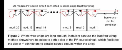
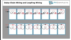
2 different series wiring methods pendant on the lead length. The skip / leapfrog method makes life easier than daisy chain.
 

Attachments

  • Screenshot_20221014-165838__01.jpg
    Screenshot_20221014-165838__01.jpg
    143.9 KB · Views: 5
  • Screenshot_20221014-165849__01.jpg
    Screenshot_20221014-165849__01.jpg
    212.6 KB · Views: 6
This is my free advice:

We start with 2 rows of panels, 10 panels connected in series. At the last PV + and PV- connection in a series, you make a 10 awg cable using PV wire and place a male MC4 on one end leaving the other end bare stripped wire. Then make a second cable using 10 awg PV wire and install an MC4 female on one end and bare wire on the other end. So now you should have both series strings having a bare wire with a PV+ and PV -. Run these wires into a suitable enclosure box near the array. If outside, the box should be nema 3R. The PV wire does not have to be in conduit if only going a short distance to the connection box. Now, hopefully your connection box will accomodate a standard DIN rail. For each series string, you will need 2 DIN rail mounted solar fuse holders and 1 double pole 600 VDC breaker of 20 amp capacity. Put 25 amp fuses in the fuse holders.
Take the PV- and connect to one side of the first fuse holder. Take the output from the fuse holder and connect to the PV- pole of the breaker. Take the output of the PV- breaker and connect to a PV- buss bar. To the PV- buss bar you will connect the black wire of a Midnite Solar lightening arrestor, 600VDC rated. Now the PV- buss bar has the PV- from the breaker, the lightening arrestor and now connect a THHN or THWN type wire , 10 awg in conduit to the PV- of the inverter. Now for the PV+ wire, you will connect the PV+ wire together with the red wire coming from the lightening arrestor and then connect this to one side of the second solar fuse holder, again with a 25 amp fuse. Connect the output of the fuse to the PV+ input of the double pole breaker. Connect the output of the PV++ breaker side to the DC disconnect switch pole, 30 amp 600VDC rated. Run THNN OR THWN 10 awg in conduit from the disconnect switch to the PV+ of the inverter.
The metal panel from and any metal posts and struts should be grounded with bare copper number 8 or 6 awg in bonded lay in connectors. the ends of this ground wire loop should be connected to a ground buss bar in your DIN rail box. Then connect bare copper from this ground buss bar to a grounding rod at the array. Also connect the green ground wire of the lightening arrestor to this ground buss. And if DC disconnect switch is metal box, ground it too at ground buss. Optionally along with the PV+, PV- wires, you can include ground wire in conduit to inverter, and connect to a grounding rod nearby the inverter.

If the system is grid tied, you can separate the AC ground source from the DC ground source. Connect the AC ground source from the utility ground to the inverter ground bar and connect the neutral white from the utility to the inverter neutral buss bar. Ground the DC from array and batteries and battery cabinets and any other DC to a ground rod. This way you are keeping DC grounding separate from AC utility grounding.

You can just use ground rod at arrays and then a second, separate ground rod near inverter for batteries and metallic battery cabinets, as long as inverter is AC grounded.

If no grid tie, you will need to bond the neutral and ground in the inverter. the actual earth ground will be a DC ground to a ground rod at the inverter area. Ground all metallic cabinets and batteries, etc to this DC ground system. If using a generator with AC ground, remove the generator neutral ground bond.
If no AC ground, then you can keep the generator neutral and bond ground for safety.
 
Back
Top