diy solar

diy solar

JK BMS CAN bus comms now possible for inverters that support Goodwe and Pylontech batteries

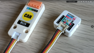
can i use two esp32 simultaneously - one connected via BT (home assistant), second connected via wire to port CAN to inverter?

one is with

second is with
Yes yes.

But one esp32 can already do both functions at once.
Report data to home assistant.
Connect to BMS over UART, send data over CAN and also fetch data over BT.
Four things at once, actually.
They're really that powerful !
 
Last edited:
Report data to home assistant.
Connect to BMS over UART, send data over CAN and also fetch data over BT.
How do you connect to HA? I thought the ESP32 can either do WiFi or BT, but not both at once? :unsure:
 
RS485 rtu slaves (BMS in this case) only reliably do comms with one master (ESP32), so expect gaps and freezes from time to time when 2 requests for data arrive at the BMS at the same time.

I have an SMA SI5048 RS485 slave feeding 2 RS485 masters, each polling every 15 secs, every 4 or 5 mins there is a glitch with wrong values and every 3 or so days the SI RS485 data chip freezes until I disconnect the 2 masters for 30 secs. If you can live with that then go ahead and try.

I agree that there should only be one master (or should I say primary/secondary or client/server)... but your experience sounds unlucky. Have just been working on some RS485 comms between my Solis and Acrel meter. The time spend on data transmission is less than 100ms for Modbus RTU queries every second. With two unsynchronised systems polling every 15s with a data transmission window of about 100ms, I wouldn't statistically expect a data collision to occur as frequently as every 4 or 5 minutes (that's only 16 to 20 transmissions) - could there be other issues, such as line termination that are causing the glitches?

Either way, is there some way you can synchronise the polling times to avoid data collisions?
 
Yes yes.

But one esp32 can already do both functions at once.
Report data to home assistant.
Connect to BMS over UART, send data over CAN and also fetch data over BT.
Four things at once, actually.
They're really that powerful !
So do You think can i mix these two yaml configs to work together on one esp32? So use free GPIO on esp32 to send data via CAN-BUS?
i think these two project and configs could have collisions (same data) have no experience with this CAN version.
 
So do You think can i mix these two yaml configs to work together on one esp32? So use free GPIO on esp32 to send data via CAN-BUS?
i think these two project and configs could have collisions (same data) have no experience with this CAN version.
There is already UART+BLE hybrid version and it is fully functional in my own home for two months now.
The approach to avoid collision is to poll sensors common to both interfaces only once.
For example, battery voltage is common to both UART and BLE.
in a hybrid file, if you're polling voltage over UART, don't do the same over BLE.
 
How do you connect to HA? I thought the ESP32 can either do WiFi or BT, but not both at once? :unsure:
This file is doing exactly that.


Connect to a JK-BMS with BLE, send that data to the inverter over CAN.
And all this while being connected to your home WIFI and reporting sensor entities for HA.
And one can even enable a webserver for monitoring on top of all that.
 
I agree that there should only be one master (or should I say primary/secondary or client/server)... but your experience sounds unlucky. Have just been working on some RS485 comms between my Solis and Acrel meter. The time spend on data transmission is less than 100ms for Modbus RTU queries every second. With two unsynchronised systems polling every 15s with a data transmission window of about 100ms, I wouldn't statistically expect a data collision to occur as frequently as every 4 or 5 minutes (that's only 16 to 20 transmissions) - could there be other issues, such as line termination that are causing the glitches?

Either way, is there some way you can synchronise the polling times to avoid data collisions?
No synchronisation possible as they are not running on the same computers, it must also be partially the individual SI as when I use the other SI the glitches are much further apart. Once I get MQTT data from my BMS with the same info I can turn one of them off. I am taking all the available parameters on one, no option to pick only the ones I want which must add to the issue.
 
This file is doing exactly that.


Connect to a JK-BMS with BLE, send that data to the inverter over CAN.
And all this while being connected to your home WIFI and reporting sensor entities for HA.
And one can even enable a webserver for monitoring on top of all that.
great thanks for sharing this config, ill try it
 
should i turn off Deye inverter before connecting esp32 with CAN-BUS on RJ45 CAN port?
 
should i turn off Deye inverter before connecting esp32 with CAN-BUS on RJ45 CAN port?
I can speak for my Luxpower unit instead,
Initially, it usually involves changing battery mode from Lead Acid to Lithium with the CAN protocol to use.
The inverter then reboots automatically.
 
hello again why in the config with ATOM esp32 lite need to use:

Code:
# +--------------------------------------+
# | ESP32 CAN/serial port pins           |
# +--------------------------------------+
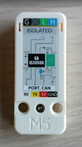
# GPIO pins your CAN bus transceiver ATOMIC CANBus Base (CA-IS3050G)
  can_tx_pin: GPIO5
  can_rx_pin: GPIO6

but connection is like on pic below GPIO 1 and 2 or i dont know smth :)

1714639583563.png
 
i have connected my CAN BUS with ATOM lite with grove port as You can see... so what configuration on yaml i should use?

Code:
# +--------------------------------------+
# | ESP32 CAN/serial port pins           |
# +--------------------------------------+
# GPIO pins your CAN bus transceiver ATOMIC CANBus Base (CA-IS3050G)
  can_tx_pin: GPIO5
  can_rx_pin: GPIO6
# GPIO pins your JK-BMS UART-TTL is connected to the grove port of Atom Lite
  tx_pin: GPIO1
  rx_pin: GPIO2

is this correct or not

Im using BT connection so i think these GPIO pins your JK-BMS UART-TTL is no use for me and i should change

Code:
  can_tx_pin: GPIO5
  can_rx_pin: GPIO6

to

Code:
  can_tx_pin: GPIO2
  can_rx_pin: GPIO1

as You can see other side of my CAN-BUS

1714640706670.png
 
but connection is like on pic below GPIO 1 and 2 or i dont know smth :)
Yes. This should be your CAN Tx and Rx GPIO pins.
GPIO pins your JK-BMS UART-TTL is connected to the grove port of Atom Lite tx_pin: GPIO1 rx_pin: GPIO2
This is where wires coming from JK-BMS go. Tx-Rx and Rx-Tx.
You can always swap the pins in software if it doesn't work in the first try.
 
  • Like
Reactions: knd
Yes. This should be your CAN Tx and Rx GPIO pins.

This is where wires coming from JK-BMS go. Tx-Rx and Rx-Tx.
You can always swap the pins in software if it doesn't work in the first try.
thanks so have all :) only need compile new yaml and will go :) i'll let You know how it works on DEYE SUN-8K-SG01LP1-EU
 
hello again why in the config with ATOM esp32 lite need to use:

Code:
# +--------------------------------------+
# | ESP32 CAN/serial port pins           |
# +--------------------------------------+
# GPIO pins your CAN bus transceiver ATOMIC CANBus Base (CA-IS3050G)
  can_tx_pin: GPIO5
  can_rx_pin: GPIO6

but connection is like on pic below GPIO 1 and 2 or i dont know smth :)

View attachment 212773
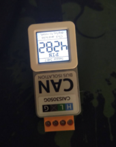
I have never been able to flash mine with HA succesfully with this combination using the Yaml yet.

1714644956120.png

i ideas why ?
 
dont know why my Atom S3 lite doesnt remember config after reset or i turn it off... strange is broken esp? or what?

Its only native esphome config... nothing else

it was problem with esphome, new version has no problems... strange
 
Last edited:
Hi,

My communication with JK-BMS and Deye is working with Atom esp32 and CAN-BUS for 1 day and i have question...

My V bulk setting is set to 54.2V and when the BMS reaches this voltage and I reach 280ah I have 100% SOC and on the Deye inverter I have 99% SOC and it does not want to terminate at 100%. Do I need to calibrate my communication somehow? I am using the PYLON 1.2 protocol

please let me know

Hi,

99% means charging is not complete. The canbus sends 100% only when the charging phase is completed when the status is EOC or Float.
 
54.2V is a very low charging voltage for LFP.

Do you use TimeOfUse with Deye?

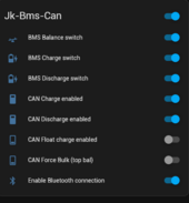
Can you send a screenshot of your BMS settings?
 
Hi,

Im using TimeOfUse but have set it no grid no gen with 20% all hours and days, so it should switch to GRID only when battery goes under 20%

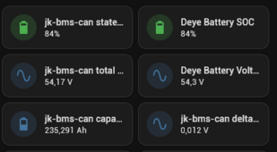
My BMS settings from HA

1714808022771.png

1714808060789.png

now it looks like this
1714808106975.png
 
Back
Top