diy solar

diy solar

What do you think is going on with this bank?

Bleedingblue

Solar Enthusiast
Joined
May 12, 2020
Messages
562
I have 10 banks of batteries
4-305s
6-280s

The 6-280s are charged in parallel all connected to a copper busbar. All have equal length cables, same model JK 2Amp balancer, same compression etc etc

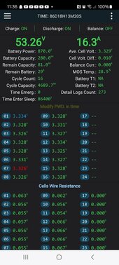
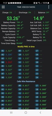
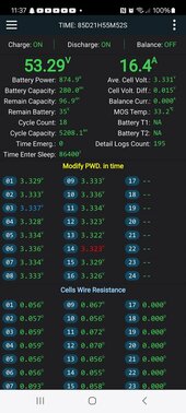
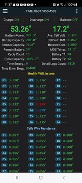
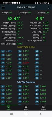
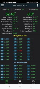
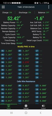
I have 1 pack of batteries that always has way more charge in it. It will hit 100% way quicker and doesn't discharge down like the others. It also has a cycle count that is crazy high compared to the others.
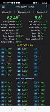
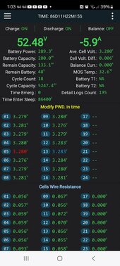
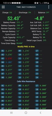
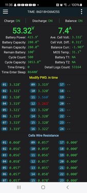
One thing I've noticed is that none of the batteries equalize each other. After charging one bank who has more current flows to another to equalize. Screenshot_20240501_113629_BMS.jpgScreenshot_20240501_113649_BMS.jpgScreenshot_20240501_113701_BMS.jpgScreenshot_20240501_113715_BMS.jpgScreenshot_20240501_113742_BMS.jpg
 
What is your absorption voltage set at for the charge cycle? Unless all the batteries reach at least 54.8V AND the charge current has tapered off to less than 2 Amps, they are not fully charged. The BMS needs to recalibrate to 100% on a regular basis.
If the batteries are constantly micro-cycled but not fully charged the BMS is going to drift with the result being a large divergence between batteries as shown in the screen shots.
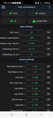
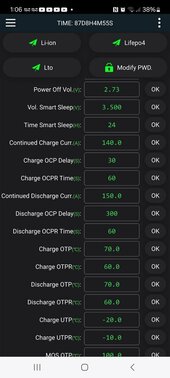
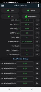
Screen shot of settings

Screenshot_20240502_010615_BMS.jpgScreenshot_20240502_010626_BMS.jpgScreenshot_20240502_010640_BMS.jpg
 
For the battery with the 502 cycle count, can you turn OFF discharge? Keep it off until you see the Cell Volt Diff less than .005v. The battery also has a crazy high Detail Logs Count. I'm guessing Over Voltage Cell protection.
 
For the battery with the 502 cycle count, can you turn OFF discharge? Keep it off until you see the Cell Volt Diff less than .005v. The battery also has a crazy high Detail Logs Count. I'm guessing Over Voltage Cell protection.

Ya I can turn off the discharge on em.
I used to have some overkill bms on em and all the banks were crazy and I switched to the JK because of the 2 amp balancers. Some of the 280s had only half the capacity because the bms would cut off charging because of cell voltage reaching over voltage protection and all the other cells only being half full.

The 305s I have are recently new having them going since last December and haven't had a problem with them.... Yet.
 
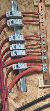
Picture and diagram of the connections/fuses to the bus bars and where the chargers connect to the bus bars?

I am asking this because of a thread on where to place leads for parallel batteries to get optimal balancing.
 
Picture and diagram of the connections/fuses to the bus bars and where the chargers connect to the bus bars?

I am asking this because of a thread on where to place leads for parallel batteries to get optimal balancing.

This is an older pic I had on my phone.
The bank in question is the third breaker from the bottom. I have another cable now going to the other set of batteries but it's further up.

Screenshot_20240502_200929_Gallery.jpg
 
Ya I can turn off the discharge on em.
I used to have some overkill bms on em and all the banks were crazy and I switched to the JK because of the 2 amp balancers. Some of the 280s had only half the capacity because the bms would cut off charging because of cell voltage reaching over voltage protection and all the other cells only being half full.
When you have time:
1) charge to the point a bms cuts off
2) set inverter to charge voltage just under that.
3) note the high cell voltage reported by the bms.
4) let the bms balance.
5) when the high cell drops by 0.010v, increase charge voltage by 0.10v
6) repeat until you hit 57.7v
7) hold 57.7 volts until hi/low cell spread on all bms is under 0.005v

For this run, you might want to raise Cell OVP to 3.640v, and OVPR to 3.638v
 
Last edited:
When you have time:
1) charge to the point a bms cuts off
2) set inverter to charge voltage just under that.
3) note the high cell voltage reported by the bms.
4) let the bms balance.
5) when the high cell drops by 0.010v, increase charge voltage by 0.10v
6) repeat until you hit 57.7v
7) hold 57.7 volts until hi/low cell spread on all bms is under 0.005v

For this run, you might want to raise Cell OVP to 3.640v, and OVPR to 3.638v

I could try and do that but would take a while. Only have a 19kw panel set up and it takes several days to charge it on full sun with my power needs.

Screenshot_20240502_210134_Weather.jpg
 
I have 1 pack of batteries that always has way more charge in it. It will hit 100% way quicker and doesn't discharge down like the others.
I would be helpful if you could screen capture that pack when it is charging & reaching "full" and things are tripping & being logged.

Pack 1, Cell 15, also has a higher resistance, might wanna check that & verify it's good & tight. Your pics do not show cells 8 & 16 but you have a couple of others that are higher resistance than others within the pack. Those are indicators of things that are just "not quite" right... Really you should only see 0.005 to 0.010 differential at most between the cells. Could be loose, bad crimp, or wire failing (the wires DO BREAK if crimped and played with a bit... super thin wire... I've had them break during install (properly crimped & never soldered).

All your Batt to Bus cables are same length & gauge as you stated but have you checked the cables resistance ? In particular check resistance of the cables to the One Quirky Pack - it could be screwy and lurking. I see two Larger Cables attached to that BUS without breakers, what are they for ?

Clarification so that we are using the Correct Terminology, otherwise muddling WILL occur.
A Battery = Cells & BMS in a Box. A Bank = set of complete batteries interconnect to act as one power storage system. This can be 2 Batteries or 20, regardless of configuration (Series, Series/Parallel or just in Parallel). A Battery Pack is not a Battery Bank. Andy has never gotten that straight in his head ad results in much confusion elsewhere when people use incorrect terms.

ASSUMPTION because you never showed it, but the Negative Busbar is the same as your Positive one ? If NOT, that could cause issues.
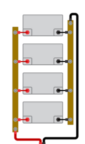
Also, are you running the (+) & (-) from each pack to busbars "together" ? If not you will get Magnetic EMI (try am AM radio and you'll know how bad it gets) Assuming they are the same there is a Wiring Trick shown in the Victron wiring guide that many miss / forget, see below.
1714738162479.png

The cables attached for Inverter/Charger are on opposite ends. Batt Cables are in sequence. Believe it or not this DOES make a difference.

NB: the 280's will reduce amps taken while the 304's will take more until they reach endamp value. Then collectively they will continue to take from Float as needed to top off and balance internally. Once ALL Packs are balanced & evel they will cross balance the packs concurrently. An OVERLY AGGRESSIVE Charge Profile can counter that by causing at least 1 Pack to connect/disconnect thereby hampering the entire bank. That "handicapped" pack will draw down the rest to it's level. This is terribly easy to observe.

Dealing with different capacity packs in Parallel. This is fine BUT there are considerations, most especially for batts with over 100AH capacity difference. I've run 1x100AH, 2x175AH, 3x280AH for almost 2 years without issues BUT use the trix ;-) 280AH & 304AH are almost like Kin and little difference. The EndAmps/TailCurrent for 280AH = 14A , for 304AH it's 15.2A, so set your EndAmps/Tailcurrent to 14.0A. When EndAmps/Tailcurrent is reached the SCC will transition from Bulk/Absorb to Float.

Again the Charge Profile RULES ! Stay moderate and do not attempt to push the cells beyond working specs. This will help manage any runners (which typically start to run once above 3.400-3.450) that end up causing HVD (High Vol Disconnects) which then handicaps that one pack. See my recommended "Works Well" profile that may are using to solve similar issues (which I ran into as well early on).

THE BIG GOTCHA !
System Calibration - ohhh so many skip this process....

Here is a Thread I wrote to address this a while back. Unless the line losses & voltage differences are taken into account you cannot guarantee the "precision" which results in random issues depending on which direction (charging or discharging). The results can be premature or LATE low voltage disconnects or triggering runner cells above the working range. You WILL need a good DMM/DVOM with at least 2 decimal accuracy.

A Voltage Chart I created which is shown a lot here is below as a reference for you.
Hope this helps, Good Luck.
quick-voltage-chart-lfp-jpg.150247
 
I would be helpful if you could screen capture that pack when it is charging & reaching "full" and things are tripping & being logged.

Pack 1, Cell 15, also has a higher resistance, might wanna check that & verify it's good & tight. Your pics do not show cells 8 & 16 but you have a couple of others that are higher resistance than others within the pack. Those are indicators of things that are just "not quite" right... Really you should only see 0.005 to 0.010 differential at most between the cells. Could be loose, bad crimp, or wire failing (the wires DO BREAK if crimped and played with a bit... super thin wire... I've had them break during install (properly crimped & never soldered).

All your Batt to Bus cables are same length & gauge as you stated but have you checked the cables resistance ? In particular check resistance of the cables to the One Quirky Pack - it could be screwy and lurking. I see two Larger Cables attached to that BUS without breakers, what are they for ?

Clarification so that we are using the Correct Terminology, otherwise muddling WILL occur.
A Battery = Cells & BMS in a Box. A Bank = set of complete batteries interconnect to act as one power storage system. This can be 2 Batteries or 20, regardless of configuration (Series, Series/Parallel or just in Parallel). A Battery Pack is not a Battery Bank. Andy has never gotten that straight in his head ad results in much confusion elsewhere when people use incorrect terms.

ASSUMPTION because you never showed it, but the Negative Busbar is the same as your Positive one ? If NOT, that could cause issues.
Also, are you running the (+) & (-) from each pack to busbars "together" ? If not you will get Magnetic EMI (try am AM radio and you'll know how bad it gets) Assuming they are the same there is a Wiring Trick shown in the Victron wiring guide that many miss / forget, see below.
View attachment 213039

The cables attached for Inverter/Charger are on opposite ends. Batt Cables are in sequence. Believe it or not this DOES make a difference.

NB: the 280's will reduce amps taken while the 304's will take more until they reach endamp value. Then collectively they will continue to take from Float as needed to top off and balance internally. Once ALL Packs are balanced & evel they will cross balance the packs concurrently. An OVERLY AGGRESSIVE Charge Profile can counter that by causing at least 1 Pack to connect/disconnect thereby hampering the entire bank. That "handicapped" pack will draw down the rest to it's level. This is terribly easy to observe.

Dealing with different capacity packs in Parallel. This is fine BUT there are considerations, most especially for batts with over 100AH capacity difference. I've run 1x100AH, 2x175AH, 3x280AH for almost 2 years without issues BUT use the trix ;-) 280AH & 304AH are almost like Kin and little difference. The EndAmps/TailCurrent for 280AH = 14A , for 304AH it's 15.2A, so set your EndAmps/Tailcurrent to 14.0A. When EndAmps/Tailcurrent is reached the SCC will transition from Bulk/Absorb to Float.

Again the Charge Profile RULES ! Stay moderate and do not attempt to push the cells beyond working specs. This will help manage any runners (which typically start to run once above 3.400-3.450) that end up causing HVD (High Vol Disconnects) which then handicaps that one pack. See my recommended "Works Well" profile that may are using to solve similar issues (which I ran into as well early on).

THE BIG GOTCHA !
System Calibration - ohhh so many skip this process....

Here is a Thread I wrote to address this a while back. Unless the line losses & voltage differences are taken into account you cannot guarantee the "precision" which results in random issues depending on which direction (charging or discharging). The results can be premature or LATE low voltage disconnects or triggering runner cells above the working range. You WILL need a good DMM/DVOM with at least 2 decimal accuracy.

A Voltage Chart I created which is shown a lot here is below as a reference for you.
Hope this helps, Good Luck.
C
quick-voltage-chart-lfp-jpg.150247


I could check the wires and see if any are broken from being crimped too tight. I usually crimped them a couple times to make sure there was a good bond. I had a couple at the start where I could pull out the wire after crimping. So I always checked them to make sure they couldn't pull out or wiggle in the lug.

But didn't have a problem until the last month or so out of the bank. Been going good for the couple months prior. I'm a set it and forget it type of person. I don't mess with stuff that's working just fine.
I checked the nuts on the batteries and all are tight. Some I could tighten a little more but don't wanna press my luck on that. Those envision 305s had very weak welded studs on em and anything over 4 NM would snap off the barely welded stud.

These batteries are prob 4 years old. They have the screw in studs on em. Have to have an Allen wrench on top and and wrench on the nut to tighten them.


The 2 big 4/0 cables you see are going to another copper bus bar that my 4 inverters go too. Right now I have another big cable going to my other 4 packs of 305s that I have on other side of the room.


The negative side is pretty much identical to the positive side. Equal length cables, same size cables etc.

Ya I understand charging in parallel where if you have the positive and negative at the first battery then that battery will be doing most of the work. So you need positive at one end and negative at opposite end
 
Last edited:
After getting home from work I cut the bms off from discharging.
The pack said 0% left. The #12 cell said 2.7 volts on the bms and the others were around 3.24.
Checked with the voltmeter and it was dead on what the BMS said.
 
Back
Top