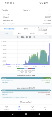
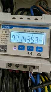
Hmm....from the video, CHINT meter displays "telephony" icon, meaning it has communication with the inverter. The CHINT meter is also located very close to your grid provider meter. So, the wiring is probably correctly done by the installer......maybe?
Hmmm........just in case if the CHINT is feeding the inverter wrong data, can you verify where are the CT clamp for the CHINT located? I am not certain if your particular CHINT smart meter model has integrated CT clamp or using external CT clamp like the one shown in this video. Please watch until finish and verify if the CHINT smart meter is the same as in the video.
Then, there is another model that doesn't need the installation of CT clamp as shown here:
Let check the wiring first. Let assume your CHINT model is not CT clamp type.
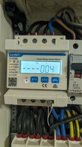
View attachment 214156
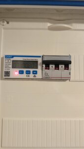
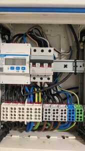
For the orange part, there should be four wires connected to the top of the CHINT. (Orange lines in the pic)
For the circled yellow part, that would be the inverter section which the wires should power up your house load.
Everything seems to be correct.
I do not know what is the B16 breaker circuit powering though, it is separate from the inverter circuit from what I can see at the wiring.
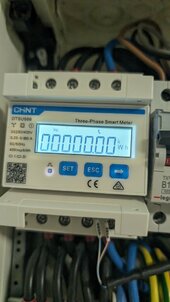
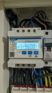
Next, check the CHINT meter setting, the password code is 701.
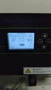
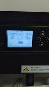
Before you make any change, tell me the current settings for PROT, Addr, Baud and NEE
For Growatt three phase using CHINT meter, the setting is:
PROT = n.1 (None parity, 1 stop bit, n.1)
Addr = 4
Baud = 9600
Nee = 0 (n.34 three phase four wire)


")