congrats on 1000 responses4
I work all the time. I keep my plate full.


You are using an out of date browser. It may not display this or other websites correctly.
You should upgrade or use an alternative browser.
You should upgrade or use an alternative browser.
Cheap 4kwh LiFePO4 batteries from Battery Hookup
- Thread starter Will Prowse
- Start date

No.Were they in a box?
Just wrapped with plastic on the pallet.
KBWaldron: have you made any more progress on your plans of Nov. 20. Your plans make much more sense to me now after a month of learning. Your plan to tie each corresponding cell together is the same idea that David Poz is using in his recent video. But OMG all those wires make my head hurt to try and follow.I purchased two of these batteries, and thought I would do the following as part of my balancing.
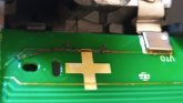
The diagram below shows the two batteries as they would be wired (black) in parallel. The inter-cell lines (thin black) are already there as some pretty significant bus bars. I would bottom balance with this arrangement, not yet having added the green connections.
Then I plan on adding the wires in green, which effectively put corresponding cells from each battery in parallel. This will cause each cell pair to become and remain balanced to each other. I would have fuses in each of these lines to protect against one of the cells in a pair shorting internally; this would not be good for the other cell, to say the least. I would then bottom balance again, now establishing an absolute bottom (i.e. the low end of charge based upon the chemistry of all cells.
At this point we do not have a fully depleted battery, which would also be a truly dead battery. Instead, it should be thought of as a battery with no available power, since the system would be configured to stop any further draw on the battery once this charge level has been reached.
Finally, I would add an active BMS, connected as usual, to keep the entire packed balanced. This arrangement has the benefit of only requiring one BMS, rather than two. Then I would charge the battery to determine the true capacity of the battery.
Now, my only concern. Have I somehow mistaken this wiring to be a safe arrangement? It can be confusing since there is a mix of parallel and serial wiring going on. Note though that the green lines go between equal voltages, and in fact, force these voltages to remain equal by bleeding current one way or another to maintain that voltage. Meanwhile the BMS will do the same thing between cell pairs to maintain a common voltage in all cell pairs.
The current through the green lines should normally be very small and so relatively light gauge wires can be used, as is the case with the BMS wires. In fact, these light gauge wires could act as the fuse I suggested, but I will still use fuses.
I invite any comments.
Edited to make green lines in diagram clearer.
View attachment 2350
KBWaldron
Solar Enthusiast
Still waiting on deliveries. I saw David Poz’s approach, which is a simpler way to do what I was planning and will replicate.KBWaldron: have you made any more progress on your plans of Nov. 20. Your plans make much more sense to me now after a month of learning. Your plan to tie each corresponding cell together is the same idea that David Poz is using in his recent video. But OMG all those wires make my head hurt to try and follow.
please inspect if you go that route, hate to see everyone taking the easy way only to have this happen with large amounts of powerStill waiting on deliveries. I saw David Poz’s approach, which is a simpler way to do what I was planning and will replicate.
Attachments
KBWaldron
Solar Enthusiast
So, better to solder larger wires to the eight cell positive, and one negative, terminals. Point taken. I’m going to still route back to the molex connector, repurposed, to keep things neat.please inspect if you go that route, hate to see everyone taking the easy way only to have this happen with large amounts of power
If you choose to solder, be sure you solder to the tinned plates attached to the boards, not to the buss bars on the battery cells... aluminum foil isn’t really suited for soldering.So, better to solder larger wires to the eight cell positive, and one negative, terminals. Point taken. I’m going to still route back to the molex connector, repurposed, to keep things neat.
rivets are better with some anti corrosion gunkSo, better to solder larger wires to the eight cell positive, and one negative, terminals. Point taken. I’m going to still route back to the molex connector, repurposed, to keep things neat.
rivets are better with some anti corrosion gunk
Yes, but there are already tinned copper joints riveted to the bars. So, soldering is an option it desired.
I still haven't received my batteries so I can only use my imagination. I am going to try and do as little to the batteries as possible. I sure hope someone solderers lead wires before me and posts pictures.If you choose to solder, be sure you solder to the tinned plates attached to the boards, not to the buss bars on the battery cells... aluminum foil isn’t really suited for soldering.
I am trying to figure out how I will use the stock fan, maybe backed up by a second fan mounted nearby. Some kind of thermostat is what I figure.
ghostwriter66
"Here - Hold my Beer"
Has anyone actually checked to see how much life is left in these batteries ?? They are suppose to have 200 aH brand new - WHAT ARE THEY NOW??
Bluemalibu
New Member
Still waiting on deliveries.
I just received a notification that my three batteries will finally be delivered tomorrow... five weeks since ordering. Sheeesh!
5 weeks, who did you order from?I just received a notification that my three batteries will finally be delivered tomorrow... five weeks since ordering. Sheeesh!
Bluemalibu
New Member
5 weeks, who did you order from?
BatteryHookup, on Nov 8th.
Bluemalibu
New Member
wtf, I picked mine up on the 14th maybe I snagged yours
The shipping label should shed some light on when they left the vendor... who knows, maybe they have just been sitting at the hub in Sacramento for a month?
Similar threads
- Replies
- 12
- Views
- 450
- Replies
- 0
- Views
- 120
- Replies
- 10
- Views
- 557
- Replies
- 17
- Views
- 782