diy solar

diy solar

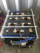
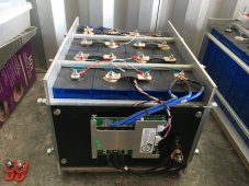
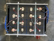
Pictures - Battery bank clamp assembly

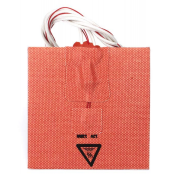
I used the Facon heating pads attached to an aluminum plate that i covered with Polyimide tape. Seems to work well. Between each cell, I used thin heat resistant rubber floor matting. I covered the inside of my aluminum toolbox with felt, and used cutting boards on top to protect each cell and house the BMS.


THANKS! The toolbox link looks interesting, I saved it just now in my Amazon Wish List to review it later when I get to the point of installation, guess I could check and confirm the dimensions based on what I got.

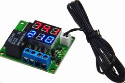
I did also get some heat pads (total of 3) that come with 3M tape on them, and I have the aluminum plate on the bottom to stick it to, also got 3 thermostats, one for each of those pads. The RV 12v pack may need it for sure. Not 100% sure where the 48v packs will actually go yet, whether they will be in a temperature controlled environment or semi-temp controlled env or what it will look like at this stage, but have the pads anyways.

1622355377824.png

1622355403300.png
 
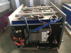
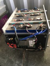
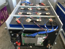
Latest pictures, showing final breaker wiring on the 12v pack. Still haven't installed any of the heating pad equipment yet though...

1624207562237.jpeg

1624207577211.jpeg
 
So two seperate 12v packs per case, with 2 x BMS. I like that. One change I would make is to move the sense wires to the positive side of the bus bars, and add some electrical insulation between the cells and also where the cells meet the aluminum plates. I like the clean look and cabling, and great work on the pack itself. Looks like the BMS's and pack terminals are well done. What will you use to protect the top of the cells to prevent accidental shorts?
 
Thanks for that suggestion, will try that (always seems to help to follow little tricks, like best practice items that could help optimize)...

As far as protection, I haven't fully decided, depends on what the install environment will be exactly. If I have it fully indoors in a temp controlled environment, then I might just have them on a shelf (like on my 48v packs planned installation). I am not sure how warm I will be able to keep the shop, where if I put them in the house, it will likely always stay within 5-10 degrees.

But this is the 12v RV pack, I may have it in a semi-temp-controlled environment, where it would be in the insulated basement of my Class A coach, and I may plan on wrapping some insulation around the pack, or make a dedicated box for it and put some kind of lid onto it, to help keep the heat that the heat pad would provide inside the heated space around the pack.
 
Last edited:
I did go out there again today and took off the 'Stinger' breakers, as I was not impressed with the way the studs were rotating on the conductors (when attempting to tighten them), and did not like the recessed connector seat problem I described before in a previous post. Seemed too hokey for my liking. So I took those off and put on some 150a Eaton (Bussmann) breakers instead. The connectors are solid and got them as tight as I wanted. Feels much better to me now.

1624224266380.jpeg
 
Last edited:
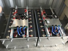
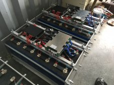
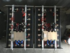
I made more progress on the 48v banks today. They are both fully operational now. I'm glad I added those 2a active balancers since they come with bluetooth management app, where the two BMS (I bought originally), are unmanaged. It is nice to be able to log into the balancers and see each cell voltage.

It's a challenge to make the wires all pretty because there are just so many (and being all the same length). Oh well, at some point you just give up and accept that it works, not worry as much about a few wires, I guess I could build a cover if I really cared about it that much. Most of the tangled up mess is hiding under the modules there.

1625452325197.jpeg

1625452351275.jpeg

1625452383695.jpeg
 
I made more progress on the 48v banks today. They are both fully operational now. I'm glad I added those 2a active balancers since they come with bluetooth management app, where the two BMS (I bought originally), are unmanaged. It is nice to be able to log into the balancers and see each cell voltage.

It's a challenge to make the wires all pretty because there are just so many (and being all the same length). Oh well, at some point you just give up and accept that it works, not worry as much about a few wires, I guess I could build a cover if I really cared about it that much. Most of the tangled up mess is hiding under the modules there.

View attachment 55079

View attachment 55080

View attachment 55081
Great work!
 
An important discovery to make note of here in my implementation of a home brew clamp assembly. A fatal flaw in my design...

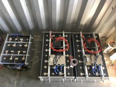
As I connected up my bus bars, on one pack (seen on right in picture), when I connected the bridge cable (little red cable) on the right-hand side 48v pack, to connect the 2 halves of that pack, I was getting a spark, and could hear a rapid discharge (like a boiling sound from one of the cells). I quickly removed it. The red bridge cable was fine if I bridged the pack on the other end (bottom end in picture). But connecting the 2 halves on the top end between the 2 halves would get a spark...

So I removed all the bus bars, did some voltage testing and found that 12 of the cells across my 3 battery banks, the negative conductor of the cell is grounding to the aluminum clamp chassis. Wow, this is bad. I disassembled all of the clamp assemblies, and found that due to the sharpness of the threads on the threaded rods, some of the cells got pierced (the blue wrap on the battery cells is very delicate, and there is aluminum casing under the blue wrap of the cells, which is apparently the same conductivity as the negative terminal).

So my advice to anyone who is using metal/aluminum clamp assemblies and fasteners which are conductive, check each cell and make sure the blue wrap is fully intact with no breaches, and negative of the cell chassis is not grounding to the clamp chassis in any way. This can cause one or more cells to have impedance or dead-shorting in relation to other cells causing a drain or short on a cell. I had some cells which just had some impedance but not like a full dead-shorting condition. This kind of thing could cause a behavior like you have a malfunctioning cell, or in my case the one which had a dead-short making it obvious for me to find.

So now to regroup in my plan. I am going to put silicone tubing along all the threaded rod sections where they run along the cells, drill the end-plate holes a bit larger to give the wiggle room for extra clearance required with the tubing installed, put some blue electrical tape over the nicks on the cells, and confirm that each cell is insulated from the clamp chassis.

So I just thought I'd mention this, as others may have the same problem without necessarily knowing about it.

View attachment 48146

View attachment 48147

View attachment 48148
There's a discussion somewhere in the forum saying something about not to trust the blue casing and use a board separator like capton sheet board or epoxy sheet board. Thanks for the idea and website to order precut materials. I've been looking to do something like yours that's portable enough to fit in a handtruck. I'm thinking of using a liquid electrical tape or liquid rubber like plasti drip to insulate the rods and perhaps the metal plates.
 
There's a discussion somewhere in the forum saying something about not to trust the blue casing and use a board separator like capton sheet board or epoxy sheet board. Thanks for the idea and website to order precut materials. I've been looking to do something like yours that's portable enough to fit in a handtruck. I'm thinking of using a liquid electrical tape or liquid rubber like plasti drip to insulate the rods and perhaps the metal plates.

Sure no prob at all... FYI, that silicone tubing I wound up using, I think was the perfect fit and finish, and it is removable in case is ever required...
 
silicone tubing to insulate threaded rod is what i will use in upcoming 300Ah cell build, also.

this thread has definitely inspired me to aspire :D
 
silicone tubing to insulate threaded rod is what i will use in upcoming 300Ah cell build, also.

this thread has definitely inspired me to aspire :D

Yeah, here is the exact link I bought mine from, it was just the perfect size to fit the 3/8" threaded rod, not too tight to be annoying to put on, but not too loose to flop around, when I put those tubes on, it was one of those times in life I just thought how that was just meant to be :love:


And I have plenty of tubing left for other homesteading projects like pumping water in a greenhouse or something...
I just go with no rubbers....? and do not bother to compress. Since I'm not mobile, no worries. I still seperate EVERY cell from each other and from the metal box using heat resistant polymer sheeting.
 
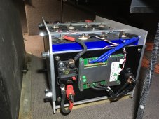
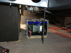
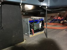
BTW, finally starting to install the 12v pack in the basement of my Serengeti... This weekend will start wiring it in along with a 250|100 Victron. About time I'm finally getting somewhere... Still aways away from getting the 48v system installed though...

1636084664878.jpeg

1636084736047.jpeg

1636084750384.jpeg
 
BTW, finally starting to install the 12v pack in the basement of my Serengeti... This weekend will start wiring it in along with a 250|100 Victron. About time I'm finally getting somewhere... Still aways away from getting the 48v system installed though...

View attachment 71378

View attachment 71379

View attachment 71380
I still looks like there is no isolation between each cell and between the cells and the frame. Take a look at the yellow panels in the Seplos Mason DIY build for what I mean.
 
I still looks like there is no isolation between each cell and between the cells and the frame. Take a look at the yellow panels in the Seplos Mason DIY build for what I mean.

I did buy some of this 3D printing tape in case I want to put some on the cell faces and clamp chassis walls:


I wasn't having issues with this 12v pack shorting out though. These cells seem a little better built than my other 48v packs have in them. I may take it apart anyway though and put this tape on. Had also been looking into kapton tape or sheets, to provide insulation. It's just silly that we even have to worry about buying a battery and it grounding out to stuff. What if car batteries were made this cheap?
 
e.g. https://www.amazon.com/gp/product/B08XM1P3TL/ this one is out of stock but i have the 3 inch wide 2 mil thick roll right here and it’s really perfect for wrapping the smaller cells that i’m currently working with. the 2 mil kapton goes on way nicer than the 1 mil thick stuff.

due to my distrust of the thin blue vinyl wrap as a robust long term electrical insulator in the presence of any pack movement, i’ve become fond of simply adding one or two extra layers of 2 mil thickness or greater kapton/polyimide tape. sourcing wide enough to get the entire big cell at once is kind of annoying i guess. have been able to find 1 mil thickness 6” wide kapton/polyimide tape but the 1 mil thickness is too paper thin for me and it’s Really Annoying to apply due to the thinness.

if you can source 6” wide kapton/polyimide tape and apply at least a layer on each cell on top of the blue stuff, it is an exceptional safety upgrade in my humble opinion. the melting temp of the tape is high and it won’t melt away easily and allow electrical contact. that’s one thing that rigid separators excel at. sorry for the ramble! the pack looks awesome! just sharing some random thoughts about electrical insulation with these big cells
 
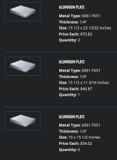
Just in case anyone would like to use the same dimensions I came up with on the plates, I posted this screen shot in another thread and though to maybe stick it here as a reference.

The first item is the qty:2 bottomside plates for the two 16-cell (longer) 48v packs

The second item is the qty:1 bottomside plate for the 8-cell (shorter) 12v pack seen in above pic

The last item is the qty:6 end plates which are compatible size for all of the banks (use 2 of them per bank/pack, on each end)...

1639941214026.png
 
Just in case anyone would like to use the same dimensions I came up with on the plates, I posted this screen shot in another thread and though to maybe stick it here as a reference.

The first item is the qty:2 bottomside plates for the two 16-cell (longer) 48v packs

The second item is the qty:1 bottomside plate for the 8-cell (shorter) 12v pack seen in above pic

The last item is the qty:6 end plates which are compatible size for all of the banks (use 2 of them per bank/pack, on each end)...

View attachment 76418
Where did you buy these plates? I was just going to use my plasma cutter and cut mine out out of a larger plate.
 
Back
Top