You are using an out of date browser. It may not display this or other websites correctly.
You should upgrade or use an alternative browser.
You should upgrade or use an alternative browser.
Relay to disconnect large inverter (Will's latest video)
- Thread starter markb
- Start date
FilterGuy
Solar Engineering Consultant - EG4 and Consumers
Got links to the products?I wonder where the idea for a SCRAM came from?
An over/under voltage disconnect/safety switch to kick a SPDT or DPDT will work without the continuous on (Normally Open) to save the batteries.
There is virtually no draw (.03W) until the protection is triggered, then the draw is whatever the relay draws.
I'm working on my first BMS, and I speculated about using it to SCRAM my battery protection relay already in place, but I just don't know enough about BMSs to recommend it for anyone yet... Good to see Will running with some last ditch battery disconnect since big versions of these batteries cost so much and are so easily damaged by low voltage!
You gave me a starting point for my 24V, 4.5kWh batteries headed for a 48 Volt system (notice the coil voltage on the relays below).
Since Will is getting shocked, that relay isn't blowout protected, bad news should the contacts wear much at all, you WILL get welding since the differential is so high, good way to get serious arc problems.
There is a reason I don't use closed high amp relays anymore, and I"ve been using them for nearly 20 years ti do exactly what he's doing,
And I started out with with a NC, continuous draw system, but it didn't take me long to figure it out and go to DPDT, blowout protected relay. I run it NC (normally closed) until something goes horribly wrong...
View attachment 5307
Under/Over voltage switch, 12, 24, 48 volt versions, $20
NO (Normally Open) allows the system to draw .03W until the under/over voltage is triggered, samples the battery line voltage.
View attachment 5308
View attachment 5309
Voltage Monitoring Relay DC 12V/24V/36V/48V Over-Voltage and Under-Voltage Protection Relay 35MM Guide Rail 13-17V 10-14V(DC24V): Amazon.com: Industrial & Scientific
Voltage Monitoring Relay DC 12V/24V/36V/48V Over-Voltage and Under-Voltage Protection Relay 35MM Guide Rail 13-17V 10-14V(DC24V): Amazon.com: Industrial & Scientificwww.amazon.com
I bet I just sent a bunch of people off on google searches...
Differential? Blowout?...
Maybe I misspelled something or used the wrong terminology for someone?
nosys70
Solar Enthusiast
- Joined
- Jan 15, 2020
- Messages
- 839
JeepHammer
Solar Wizard
- Joined
- Nov 15, 2019
- Messages
- 1,149
yes, never heard about such wire before.
No offense, but that's what I figued and why I pointed it out.
DO THIS STUFF about 20 years and IKSS (I Know Some Shyte)
Got links to the products?
According to gnubie we aren't supposed to 'Spoon Feed' or 'Serve Up On A Silver Platter' or whatever it was he wrote when someone was looking for a 65 amp breaker.
BIG RED WARNING, DO NOT, UNDER ANY CIRCUMSTANCES USE ANY OF THIS FOR YOUR SYSTEM.
According to 'Internet Experts' ALL of this will burn your house down, knock down the mailbox, knock up your dog, and none of it will work anyway since it's not sold through a vendor for 'Solar Equipment'.
Warning required by moderators...
But, I'm all about DIY and helping out, so what products are in question?
Some I still have the links for, some I ordered a while back and probably don't.
I have a tendency to delete things once the item comes in.
Fusible Link, scroll down for the size you think you might want...
Under/Over Voltage Monitor, DPDT so you can run a Normally Closed or Normally open.
Make sure you pick the right voltage and use a test light to set your OPEN/CLOSE points before hooking up to the battery line contactor.
Amazon.com: PBZYDU Over-Voltage and Under-Voltage Protection Relay, DC 12V/24V/36V/48V(DC48V) : Industrial & Scientific
Buy PBZYDU Over-Voltage and Under-Voltage Protection Relay, DC 12V/24V/36V/48V(DC48V): Voltage Monitoring Relays - Amazon.com ✓ FREE DELIVERY possible on eligible purchases
www.amazon.com
Panel Strings,
*IF* you want to use an upper/lower limit on the panel side, the appropriate high/low (Set low to zero or disable) and these for the panel strings. Get yours in your battery voltage, this one is 48 volt coil.
Siemens 3TX7130-0RD03 Basic Plug In Open Power Relay, DPDT Mag Blowout Contacts, 40A Contact Rating, 48VDC Coil Voltage: Amazon.com: Industrial & Scientific
Siemens 3TX7130-0RD03 Basic Plug In Open Power Relay, DPDT Mag Blowout Contacts, 40A Contact Rating, 48VDC Coil Voltage: Amazon.com: Industrial & Scientific
www.amazon.com
Latching The Relay.
If you run a normally closed protection, activation opens the relays, and you can latch any of the relays open with some 5 amp diodes, but they are everywhere and cheap, you shouldn't have to look for them very far.
Stays open once 'SCRAM' happens until you reset it.
Contactor,
And here is the rub about posting specific links, they are out of stock, but this one is 48 volt coil anyway.
It will give you a place to start a search for your battery voltage.
200A 48V DC Coil Contactor, Double Pole Double Throw (DPDT) USA Stock, NEW!: Amazon.com: Industrial & Scientific
200A 48V DC Coil Contactor, Double Pole Double Throw (DPDT) USA Stock, NEW!: Amazon.com: Industrial & Scientific
www.amazon.com
MICRO VOLTAGE CONTROL,
If you want micro voltage control, and some of us do, try this with a 'Kicker' relay for higher amperage to the big contactor.

Voltage Detection Charging Discharge Monitor Switch Control Module DC 12V Relay | eBay
Find many great new & used options and get the best deals for Voltage Detection Charging Discharge Monitor Switch Control Module DC 12V Relay at the best online prices at eBay! Free shipping for many products!
www.ebay.com
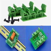
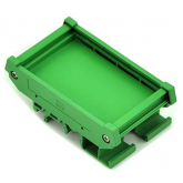
DIN Tray, (I like DIN rail boxes)

PCB DRG-01/02/03/04 DIN Rail Adapters Circuit Mounting Board Holder Bracket New | eBay
Find many great new & used options and get the best deals for PCB DRG-01/02/03/04 DIN Rail Adapters Circuit Mounting Board Holder Bracket New at the best online prices at eBay! Free shipping for many products!
www.ebay.com

Make sure you pick the right size for the circuit board you order, there are a BUNCH of sizes...

Last edited:
Bob B
Emperor Of Solar
- Joined
- Sep 21, 2019
- Messages
- 8,852
Responding to the original post ..... I am retired now, but worked many years doing commercial building controls ..... and installed and thousands of relays / contactors. The only time I ever saw the contacts fuse was when the system was struck by lightning.
If really concerned about the contacts sticking closed .... just put a 2nd relay in series with the first. The odds of 2 relays fusing at the same time is exponentially less likely ... the problem of a single failure is already EXTREMELY unlikely.
If really concerned about the contacts sticking closed .... just put a 2nd relay in series with the first. The odds of 2 relays fusing at the same time is exponentially less likely ... the problem of a single failure is already EXTREMELY unlikely.
JeepHammer
Solar Wizard
- Joined
- Nov 15, 2019
- Messages
- 1,149
Got links to the products?
Weren't you in on the Fuse/SCRAM conversation?
I posted everything including wiring diagrams there...
Even posted some pictures of component pieces as they trickle in from 'China Mart'.
SCRAM solar panels on overvolt panel overvolt situation. (Set Under Volt To Zero),
Protecting the Batteries with Panel/Charge Controller SCRAM, Over Volt on the battery line is fixed by opening panels, panels and charge controller are taken off line in one stroke.
I'm more concerned with undervolt on the batteries, I REALLY don't want to damage those expensive batteries!
Take out latching Diodes and and the circuit will close when voltage comes back into tolerance.
You could use MOSFETs instead of electromechanical relays, I simply prefer relays.
Since in a well balanced system this should never trip, but it's insurace to keep those expensive batteries alive.
Last edited:
JeepHammer
Solar Wizard
- Joined
- Nov 15, 2019
- Messages
- 1,149
Responding to the original post ..... I am retired now, but worked many years doing commercial building controls ..... and installed and thousands of relays / contactors. The only time I ever saw the contacts fuse was when the system was struck by lightning.
If really concerned about the contacts sticking closed .... just put a 2nd relay in series with the first. The odds of 2 relays fusing at the same time is exponentially less likely ... the problem of a single failure is already EXTREMELY unlikely.
With no fuse and no blowout protection, lets hope...
Maast
Compulsive Tinkerer
I might have missed it, but I havent seen any mention of a flyback diode yet. You need one on large (50A+) relays/contactors to provide a path for the spike of voltage and current the relay coils generate when the relay de-activates. Otherwise the spike hits your equipment and causes premature wear on components or can cause things to fail.


JeepHammer
Solar Wizard
- Joined
- Nov 15, 2019
- Messages
- 1,149
Why not just get an Over/Under Volt protection relay and set the timer for the delay, again, about $20
JeepHammer
Solar Wizard
- Joined
- Nov 15, 2019
- Messages
- 1,149
I might have missed it, but I havent seen any mention of a flyback diode yet. You need one on large (50A+) relays/contactors to provide a path for the spike of voltage and current the relay coils generate when the relay de-activates. Otherwise the spike hits your equipment and causes premature wear on components or can cause things to fail.
View attachment 5328
And there it is!
I was waiting from my first post for someone to argue terminology...
I bet I just sent a bunch of people off on google searches...
Differential? Blowout?...
Maybe I misspelled something or used the wrong terminology for someone?
gnubie
Solar Wizard
- Joined
- Sep 20, 2019
- Messages
- 3,844
I might have missed it, but I havent seen any mention of a flyback diode yet. You need one on large (50A+) relays/contactors to provide a path for the spike of voltage and current the relay coils generate when the relay de-activates. Otherwise the spike hits your equipment and causes premature wear on components or can cause things to fail.
It's normal for snubbers to be used across coils to prevent the kick from killing drive components. In this case it would be protecting the FETs in the BMS. The body diode in the FETs may not be capable of handling the voltage involved and break down. I imagine several people posting here are quite familiar with the use of diodes to prevent this but just hadn't thought to post it.
gnubie
Solar Wizard
- Joined
- Sep 20, 2019
- Messages
- 3,844
I'm glad YOU said that, I get in trouble for arguing with the 'Experts', fan boys and salesmen...
I even tried to get some of the guys most active and pretty well knew what they were talking about, mentioned fusing and protection circuits (SCRAM) and got mostly crickets...
You may find that people you involved in your group private message may well have been going to add some information to it but your snarky comments has resulted in them abandoning that because they no longer want to know about it. Attitude is a miraculous thing.
gnubie
Solar Wizard
- Joined
- Sep 20, 2019
- Messages
- 3,844
I can't see anyone arguing the terminology, especially not Maast who merely used a correct term. I guess me calling it a snubber must also be an argument.And there it is!
I was waiting from my first post for someone to argue terminology...
JeepHammer
Solar Wizard
- Joined
- Nov 15, 2019
- Messages
- 1,149
It's normal for snubbers to be used across coils to prevent the kick from killing drive components. In this case it would be protecting the FETs in the BMS. The body diode in the FETs may not be capable of handling the voltage involved and break down. I imagine several people posting here are quite familiar with the use of diodes to prevent this but just hadn't thought to post it.
Where EXACTLY is the 'FET' in what was posted?
And what EXACTLY does it do when not protecting a 'Fet'?
I wonder why they didn't mention it?
Seems important enough that about all high amp contactors have them installed, Will looked for contunity between coil posts, so clearly this battery protector intended for self jump starting doesn't have one...
Fairly important detail to leave out, particularly for people that are familiar with with it...
JeepHammer
Solar Wizard
- Joined
- Nov 15, 2019
- Messages
- 1,149
You may find that people you involved in your group private message may well have been going to add some information to it but your snarky comments has resulted in them abandoning that because they no longer want to know about it. Attitude is a miraculous thing.
That's a report, I'm not going to argue with you yet again.
Condensation yet again and we just went through this, Argumentative, counter productive, particularly when I contributed to the conversation...
gnubie
Solar Wizard
- Joined
- Sep 20, 2019
- Messages
- 3,844
God knows why I bother but given that the application is the coil being switched by the BMS and that the BMS uses FETs to control the load I'm suggesting that in this application the diode would be protecting the FETs. I know, what a leap!
Perhaps you should read the wiki article to understand the application and function of the flyback (snubber) diode.
Perhaps you should read the wiki article to understand the application and function of the flyback (snubber) diode.
JeepHammer
Solar Wizard
- Joined
- Nov 15, 2019
- Messages
- 1,149
God knows why I bother but given that the application is the coil being switched by the BMS and that the BMS uses FETs to control the load I'm suggesting that in this application the diode would be protecting the FETs. I know, what a leap!
Perhaps you should read the wiki article to understand the application and function of the flyback (snubber) diode.
First off, like I pointed out and you refuse to acknowledge, Will checked for continuity between posts. No diode.
So, No diode, no 'Fly Back' or 'Snubber' position.
*IF* there is no diode, that non-existent diode can't function as a blow out diode either.
Second, Diodes are a device/component, they do a LOT of functions in different positions.
I know you struggled with diodes in bypass position, and the blocking positions,, you wouldn't comment on Isolation position for diodes so i assumed you understood that...
Is that what you are upset about? The function of the position of a diode?
offgriddle
"FOREVER BEGINNING"
Clear and concise explanation with no razzle dazzle, thank you.Hi. The Relay does not affect charging at all. All it is doing is allowing literally a high amperage direct circuit from the battery to the inverter bypassing the BMS.
Going to over simplify this but we normally run 600aH 12V banks consisting of (3) 200aH batteries ... The 200A BMS we use runs us about $70. Not the best one in the world but does 100% of what we need. We put one on each battery bank.
Then we use a 12V 500A RELAY between the last battery and the inverter. Our power draw is no more than 400A at a time with no surge. Its cheaper for us to do it that way - with literally the same results - then buying 600A BMS's for each of the battery banks.
Our batteries are rated at 2C discharge.
We have buss bars that are rated at 600A
We use 4/0 from the last battery to the relay to the inverter. (slight overkill)
We fuse it
offgriddle
"FOREVER BEGINNING"
You know as I read all of these many wonderful articles that you all contribute to Will's DIY, the technical depth is impressive and even sometimes so mind boggling that I sometimes flirt with the idea of just giving in and building the $15,000, (that's a huge number for me at this point in my life), power line in from the main road to my tajmahcabin, then paying too much for grid power for the rest of my days. Then I say, "nah".
Steve_S
Offgrid Cabineer, N.E. Ontario, Canada
That's the "I'm Overwhelmed" and Overloaded feeling with too much info a hand, which get's folks exasperated and stressed. Sometimes too much info is just detrimental if it's too fast and can't be digested & understood.You know as I read all of these many wonderful articles that you all contribute to Will's DIY, the technical depth is impressive and even sometimes so mind boggling that I sometimes flirt with the idea of just giving in and building the $15,000, (that's a huge number for me at this point in my life), power line in from the main road to my tajmahcabin, then paying too much for grid power for the rest of my days. Then I say, "nah".
Similar threads
- Replies
- 3
- Views
- 1K
- Replies
- 15
- Views
- 573
- Replies
- 178
- Views
- 9K


