diy solar

diy solar

Open Source Microconverter

I was exploring what efforts, if any, have been made in the realm of open source for microconverters
Open source in the sense of polling micro inverters for data? There are standards for controlling their output like CA Rule 21 and UL1741 and others.
 
Last edited:
I’d like to see the results on the Hoymiles before I jump in. Will focus on my ground mount this winter. But I’d like so me nice 450 watt new panels on the roof with micros eventually.
 
I have recently designed an ultra simple mppt solar controller that is entirely hardware, no microcontroller, no software. It just uses a single readily available low cost pwm controller chip. Its very spartan with absolutely no frills, but it does work very well. If it ever does blow up, very easily repairable.
It maintains a constant solar panel voltage (set with a potentiometer) and charges a battery up to a set charging voltage. That is really all that is necessary.
Ideal for lithium, not really appropriate for lead acid.

The only difference between this and a "smart" software driven mppt controller, is that the software finds the max power solar panel voltage.
With this, you have to adjust the voltage yourself manually. But as the rating plate fitted to every solar panel tells you the maximum power voltage, that is not really a disadvantage.
Even if you don't know the max power voltage of your panels, its simple to just to tweak the potentiometer up and down for maximum charging current during bulk charging.
There will be a definite maximum. Its not really a sharp peak, but a very broad hump, and adjustment is not in the least bit critical.

I doubt if there will be any interest shown at all here, Folks on this forum seem to be more into buying Chinese boxes than home building anything.

But it's not really a MPPT since it has no "Maximum Power Point Tracking" algorithm. Sounds like you have created a basic buck converter with the ability to maintain constant PV voltage. I'd try one!

Maybe you could call it FPP ("Fixed Power Point")?
 
Last edited:
Yes it definitely does track the maximum power point.

The maximum power point occurs at a very specific solar panel voltage.
If loading on the panels is less, obviously less power then goes into the load.
If you overload the panels, try to draw more power than is available, then that pulls the voltage right down off the peak, and output power also falls.

The trick in obtaining maximum available power is to load the panels just enough to keep the solar panel right at the maximum power voltage.
If the sun goes behind a cloud, the load on the panel must be throttled back to prevent the voltage from falling.
That can all be done with a very simple shunt voltage regulator that self adjusts the loading to maintain a constant voltage at the panels.

Now its perfectly true that the actual peak power voltage DOES change with insolation and ambient temperature, but not by very much.
Its also true that the power peak is actually a very shallow hump, not a very sharp peak.
What does change very dramatically is insolation, that varies from zero at night to maximum in a clear blue mid day sky.

If you can track that, and maintain a constant panel voltage, over a very wide range of insolation you will do just as well as with a smart software perturb and observe algorithm.
Its certailny a lot faster acting !
And no chance the software can latch onto a false peak, as sometimes can happen.

Lots of different arguments, but in the end it is cheap, simple, easily repaired and works very well.
It also lends itself well to one low powered solar controller per series string.
If panels are of mixed type, not all in exactly the same orientation, or if some strings suffer from marginal shading, a bunch of seperate small controllers might easily beat a single central higher powered smart controller.

There is also redundancy. If you smoke your single big high power smart controller you are screwed.
If you have multiple small controllers, plus spares, its not going to be such a big disaster.
 
Now its perfectly true that the actual peak power voltage DOES change with insolation and ambient temperature, but not by very much.
I agree w.r.t. insolation, but temperature? Maybe if you're on the beach in Monterey where daytime temp is almost always between 10-25C. But there are plenty of places where daytime temps can vary by 60C and panel temps can vary even more. That can move Vmp enough to push you off that "shallow hump".

I guess you could reset your device each season and get reasonably close. But that's not MPPT any more than someone who adjusts panel tilt seasonally has "single axis tracking".
 
Yes it definitely does track the maximum power point.

The maximum power point occurs at a very specific solar panel voltage.

The MPP changes based on current conditions such as insolation, temp, and longer term cell degradation. This is why a MPPT algorithm is there to find the new MPP constanly.

Still sounds to me like you're fixed. Are you going off the MPP spec from the panel? If so that's based on STC, and will be different, and ever changing in the real world.

I'd be interested in looking at your schematic, can you share?
 
All you say is true.

But if you actually look at the numbers and do some testing, you will find that the peak power voltage does not move very far from what is printed on the solar panel rating plate.
If you experimentally adjust loading to change the operating point up and down, the change in measured power is absolutely minimal around the cusp
Its all far less critical than many people believe.

If you are chasing that very last one or two percent, then perturb and observe will be theoretically better. No argument there.

But in a practical application, its easy to just to add an extra panel and easily gain more than one or two percent !

Solar panels have fallen dramatically in price, so the low cost way to increase power is to just add panels.
The exception to that might be on a boat or RV, but for most of us, fitting more panels is the low cost way forward, rather than fretting too much about minimal drops in efficiency.

There is also an unexpected advantage of running panels at a fixed voltage I have just discovered.

Suppose you have a series string of three, and max power is at 140 volts. At dawn the controller will draw zero from the panels until the voltage reaches 140. It then begins bulk charging, maintaining 140 volts at the panels.
When the battery reaches full charging voltage, the charging current begins to taper off, and not all the available solar power can be used.

The solar voltage then starts to rise above 140 volts.

Now suppose you have another charge controller set to 142 volts connected to the same solar panels.
It will do nothing until solar rises to 142 volts, and that will not happen until the battery has completed bulk charging.

Its then possible to divert all the SURPLUS solar power above what is being used to charge the battery into something else, such as heating water, or a secondary battery bank.

Requests of how to do something like this seem to come up fairly frequently on the Forums.
 
Circuit diagram, sure no problem.

There are two error amplifiers, the first one regulates solar voltage, such that duty cycle increases if solar voltage tries to rise.
The second error amplifier regulates battery voltage. Duty cycle falls as battery voltage tries to rise.
Whichever error amplifier requests a reduction in duty cycle gets control.
It could not be any simpler.

J1 and J2 are plug in screw terminal blocks. The external wiring, mosfets, choke and diode all remain attached to the heatsink, so the circuit board just unplugs from that. Power components depend on the voltage and current requirements obviously, so are not specified.

Still playing with compensating the error amplifiers. At the moment they both have simple type 1 compensation, slow but stable, and entirely adequate. I will revisit that a bit later, but it works fine as drawn.
 

Attachments

  • Analog MPPT.jpg
    Analog MPPT.jpg
    181.5 KB · Views: 25
An excellent write-up John.
You are quite right, its a complex thing to do, and unless there is a very specific reason, just not worth all the trouble.

I have recently designed an ultra simple mppt solar controller that is entirely hardware, no microcontroller, no software. It just uses a single readily available low cost pwm controller chip. Its very spartan with absolutely no frills, but it does work very well. If it ever does blow up, very easily repairable.
It maintains a constant solar panel voltage (set with a potentiometer) and charges a battery up to a set charging voltage. That is really all that is necessary.
Ideal for lithium, not really appropriate for lead acid.

The only difference between this and a "smart" software driven mppt controller, is that the software finds the max power solar panel voltage.
With this, you have to adjust the voltage yourself manually. But as the rating plate fitted to every solar panel tells you the maximum power voltage, that is not really a disadvantage.
Even if you don't know the max power voltage of your panels, its simple to just to tweak the potentiometer up and down for maximum charging current during bulk charging.
There will be a definite maximum. Its not really a sharp peak, but a very broad hump, and adjustment is not in the least bit critical.

I doubt if there will be any interest shown at all here, Folks on this forum seem to be more into buying Chinese boxes than home building anything.
this sparks my interest!

very curious what components etc.

as always thank you for the interesting research to read about!
 
Components might vary a lot from a 12v system, up to high voltage system with perhaps hundreds of volts.
That is another advantage, you are not limited to what is commercially available.
Its only really the power components that vary, and maybe the resistors in the potentiometer voltage tweaking part.
The control board will remain pretty much standard.

The two small dc power supplies SM-12 are really the guts out of a standard 12v dc wall pack. These are available on e-bay for about two dollars each.
https://www.ebay.com.au/itm/302088719078
They are specified to supply a fully isolated 12v at 450mA for ac inputs of between 80v and 260v.
If lightly loaded, they work fine from about 30 to 35v dc input up to about 400v dc input.
My system runs at 100v (with thirty lithium cells), so for me it was a good solution.
For lower voltage solar controllers something else might be more appropriate.

Mosfets, diode and heatsink need to be adequately rated, but that should be quite straightforward.

The choke is probably the most difficult thing to nail down, but I am using some old ten amp dimmer chokes I already have, and they work fine.
These are rated at ten amps and 1mH. I might try to source something suitable from China later, but its not something I need myself right now.
But these commercial dimmer chokes are available off the shelf, and seem to work fine.
A very quick internet search turned up this:
https://www.geo-technik.de/en/Remin...-Inductors/Dimmer-Filter-Choke-11A--2025.html
Dimmer chokes for 120v are usually 0.5mH, and dimmer chokes for 230v are usually 1mH. Either should work pretty well for you.

Dimmer chokes are available up to at least fifty amps, but for one series string of panels, ten to twelve amps rating should be fine.
 
Circuit diagram, sure no problem.

There are two error amplifiers, the first one regulates solar voltage, such that duty cycle increases if solar voltage tries to rise.
The second error amplifier regulates battery voltage. Duty cycle falls as battery voltage tries to rise.
Whichever error amplifier requests a reduction in duty cycle gets control.
It could not be any simpler.

J1 and J2 are plug in screw terminal blocks. The external wiring, mosfets, choke and diode all remain attached to the heatsink, so the circuit board just unplugs from that. Power components depend on the voltage and current requirements obviously, so are not specified.

Still playing with compensating the error amplifiers. At the moment they both have simple type 1 compensation, slow but stable, and entirely adequate. I will revisit that a bit later, but it works fine as drawn.

Have you thought about ditching the diode, and using a synchronous buck driver instead? Make it run cooler, and more efficient.

Also, one thing that worries me is failure of trimmer pots. On your circuit if the wiper of the trimmer fails/disconnects what happens to the output voltage? Does it drop, or rise?

I've entertained the idea of using buck converters like this. They will work, but there will be time where a real MPPT will outperform.
Would be interesting to get some real testing/comparison data.
 
Many things are possible, my aim was to keep all this as simple and low cost as possible, its still just a prototype anyway.

At higher voltages, diode loss becomes far less significant.
If this was a twelve volt fifty amp controller, sure an active synchronous diode would be an absolute must have !

In my case I have 140 volts coming in, 100 volts coming out and diode duty cycle never gets above about 58%
For about ten amps, and a perhaps 0.8v diode drop that's 4.6 watts lost out of 140 watts maybe 3%
It would not be difficult to replace the diode with another mosfet, but I just did not think it worth the trouble.
 
Have you thought about ditching the diode, and using a synchronous buck driver instead? Make it run cooler, and more efficient.

Also, one thing that worries me is failure of trimmer pots. On your circuit if the wiper of the trimmer fails/disconnects what happens to the output voltage? Does it drop, or rise?

I've entertained the idea of using buck converters like this. They will work, but there will be time where a real MPPT will outperform.
Would be interesting to get some real testing/comparison data.
Oh there are lots of failure modes possible with any solar controller, even the very expensive commercial ones.
Not much you can really do about that at the controller.

The place to solve that problem is with an over voltage disconnect at the battery.
 
Oh there are lots of failure modes possible with any solar controller, even the very expensive commercial ones.
Not much you can really do about that at the controller.

The place to solve that problem is with an over voltage disconnect at the battery.

Yup, I had a controller short a mosfet, and tied PV directly to battery. I came up with a solution here

I used to build, mod, and service tube amps. Those trimmers used to fail frequently, sometimes in a real bad way.
 
Many things are possible, my aim was to keep all this as simple and low cost as possible, its still just a prototype anyway.
Great idea!
I'd love to get a simple microconverter to play with and learn on, but they all seem to be proprietary.
I've done this already with a cheap PWM on a small hobby PV system and that was very instructive.
One question though: since their output is ac how do you get them to sync when adding several together? And this would be very desirable that they be modular and additive.
 
I have recently designed an ultra simple mppt solar controller that is entirely hardware, no microcontroller, no software. It just uses a single readily available low cost pwm controller chip. Its very spartan with absolutely no frills, but it does work very well. If it ever does blow up, very easily repairable.
It maintains a constant solar panel voltage (set with a potentiometer) and charges a battery up to a set charging voltage. That is really all that is necessary.
Ideal for lithium, not really appropriate for lead acid.
Warpspeed,
- Very nice, thanks for publicizing your circuit.
- Is it just me, or is analog circuit design a dying art? Microcontrollers are certainly the easy way to go and offer a lot of flexibility/functionality, but analog design can get a lot of the same things done. It does require experience and creativity.

Separate question: The Oz Inverter in its present form is very nice, and obviously robust. Is there a way to have a stripped-down LF inverter without any bells and whistles? How simple could the circuit be if we had no alphanumeric displays, temperature sensors, etc. Just input lugs and output lugs with >maybe< an LED to tell of an overvoltage, etc? Icing on the cake: the dumpsters here are filled with commodity-grade countertop microwave ovens from the PRC that seem to last about 3 years. If the big transformers in them are still good and could be used in any way, they could be had for nothing.

Mark
 
Analog circuitry is definitely alive and well. Even switching power supplies require some analog. Any software "machine" still needs to interface with the real world. Most sensors still produce an analog output. Radio and microwave is all analog, and on it goes....

But you are right. These days really experienced analog designers are becoming pretty thin on the ground.

The problem with most projects these days seems to be that they are planned and designed mostly by software geeks.

Oh, we must have a graphical user interface with touch screen, and an internet connection, plus wifi on this inverter (or whatever it is).
How nice it would be to be able to check the voltage of every cell of my home battery on my mobile phone, while I am visiting overseas.
That sort of nonsense is expected these days.

The need for a very simple robust bare bones absolutely bullet proof inverter, that is very easy to both fault find repair, is not a popular concept.
Nobody wants that. They expect "features".

My concept with all of my own home built equipment is to build something as solid and simple as possible that works and is reliable.
Then add any monitoring and protection or extra features seperate and outside of that.

The basic functionality remains, if the external monitoring crashes or blows up it will still basically work.
And if the inverter, solar controller, or whatever it is itself fails, its very simple swap in a spare, and repair what failed. Fixing it should be easy, because its all been kept as simple as possible with the fewest easily accessible parts.

The Oz inverter started out with the low cost Chinese EGS-002 driver board. That worked, but was very prone to spontaneously blowing up mosfets.
My own theory about that, is that the Chinese software had a few hidden bugs. So us Aussies started to develop our own driver boards for the Oz inverter using a Nano microcontroller. That has worked out wonderfully well, and solved all the problems, but it has suffered from the "added features" disease along the way.
That is a pity, but its what most people expect these days.

Microwave oven transformers are quite small, and welded solidly together. Not ideal for an inverter of any reasonable power level.
A much better bet would be to do some dumpster diving, to find a dead grid tie inverter and rewind the toroidal transformer from that.
That is what the Oz inverter guys all do. In fact it common to stack two toroidal cores for increased power rating.
By recycling the copper wire, its possible to make a very nice efficient high powered inverter transformer at practically no cost.
 
Yup, I had a controller short a mosfet, and tied PV directly to battery. I came up with a solution here

I used to build, mod, and service tube amps. Those trimmers used to fail frequently, sometimes in a real bad way.
Brad,
What exactly is that rather nice programmable voltage controller, and where can I get one ?
I have very poor hearing and its difficult for me to get all the details from your excellent video.
 
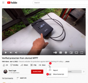
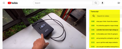
@Warpspeed You can view transcripts of videos on YouTube. (1) Click the ellipsis, then (2) click "Show transcript"
2022-09-16_08-17-53.png
and the transcript will appear on the right:
firefox_2022-09-16_08-18-36.png

You're welcome! When I learned of this, I wondered how could I have been a viewer of YouTube so long and not known about this feature.
 
Back
Top