diy solar

diy solar

XW Pro Wattnode question

2strokeforever

New Member
Joined
Dec 12, 2022
Messages
31
If anyone has a XW pro working with a wattnode I could use a hand figuring out how to set it to zero export.
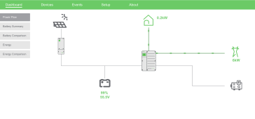
There is a bug in the software where the dashboard screen says the opposite flow direction to the wattnode screen.

What I would like to know is:
Which way is current flowing?
What color are the Leds on the wattnode?
What flow direction on the dashboard?
What would you set the export limit at to use 1kw from the grid before the inverter starts chipping in? 1000w or -1000w?

If you are running a heavy load and suddenly shut it off does it let some power back to the meter, or is it truly zero export?
Have you seen"RED" flashing on your power meter? (reverse energy detected)

I have sent a dozen emails and a video back and forth with schneider before they admitted/ figured out that the screens were reversed (which I very clearly explained each and every email). I dont trust the guy I was talking to enough to risk hooking it up backwards.

I am not allowed to sell, otherwise I would flip a coin and see what happens. I have no idea how sensitive the new power meters are to reverse flow, and dont really want to talk to the power company.

Heres a link to the video I send schneider that shows my problem.
 
I am Interested in a watt node because I have a XW-Pro Just commissioned in early January
The Inverter didn't work right until it was Reset to factory settings. My Build is BN 49.
The current flow will show going out all the time when the load of the Critical Loads is being satisfied by the inverter and the inverter is in sell mode. What the inverter doesn't know is the amount of load on the AC 1 input side of the inverter. So until the loads current on the input side of the inverter are supplied, then and only then the Net meter will show a wattage going back to the grid. Yes this is the reason for the integration of the watt-node meter and the CT on the Grid side. So for this to work correctly there would really need to be 2 CT's, one on the Grid side and one on the inverter input side of the installation. I would assume the Inverter has a current measuring device built in on the AC 1 input side of the inverter and then the one installed with the watt-node on the grid side. The integration could then know the current on the loads of the regular loads panel, and the excess current available for export. This is me thinking out loud. The out put line on the Dashboard that goes to the grid is not representative of the watt- node installation with the CT between the utility grid and the Loads panel. My guess the programmers at Schneider haven't a clue about the Electronics installation specifically the watt-node Mod and as such doesn't know what really needs to go on here with the animation on the Dash Board. If they did you would see a second loads panel and another T in the current paths one to the Grid side loads panel and the other node to the net meter. Seems to me this animation would be easy to implement with the electrical watt-node communication integration already done. Sometimes, I think Schneider Electric follows the path of least resistance in any of their implementations. Get it done and shove it out the door.
If there is anyone else that has further knowledge about this modification, I would be interested. I am also looking into the use of Emporia, a whole home metering system integrated into Home Assistant. This type of installation could be customize to display the information we all want to obtain a net zero system and not have to pay those greedy energy expletives their graft.
 
Last edited:
@2strokeforever, did you get it working? I was having the same problem with the Wattnode and I just got it working last night. I was watching this video
and then one of the commenters said they installed the Wattnode CTs according to the Wattnode instructions. But there is an Solution Guide paper from Schneider at https://solar.se.com/eu/wp-content/...l-Limiting-Solution-Guide-990-91371_rev-A.pdf.

The pictures show the CT pointing toward the panel, not the grid. This is similar to the existing CT I'm using with the Enphase Envoy meter. Both the Enphase production and consumption CTs point away from the sources and to the panel loads. I had installed the Wattnode supplied CTs pointing to the grid.

I didn't want to rip the panel apart so I was reading the CTLSys page here https://ctlsys.com/support/negative_power_values/ that said it was ok to switch the polarity of the CT (.333VAC style CTs) wires when energized, so I did and rebooted everything and sell to grid started up from the XW pro.

The funny thing is the "Meters: Wattnode 1" view on InsightLocal show the "Total energy exported" as incrementing when I'm really importing energy from the grid and "Total energy imported" counts up when solar is exporting.

However, in the InsightLocal dashboard and InsightCloud interface, the energy flows are shown import/export directions and history reported correctly.
 
@2strokeforever

I have a wattnode. If the "Flow" is reading backwards.. you have 2 options.

- Pop the CT's off, and reverse them on the wire
- remove the CT wires from the terminal blocks, and reverse them
 
I am Interested in a watt node because I have a XW-Pro Just commissioned in early January
The Inverter didn't work right until it was Reset to factory settings. My Build is BN 49.
The current flow will show going out all the time when the load of the Critical Loads is being satisfied by the inverter and the inverter is in sell mode. What the inverter doesn't know is the amount of load on the AC 1 input side of the inverter. So until the loads current on the input side of the inverter are supplied, then and only then the Net meter will show a wattage going back to the grid. Yes this is the reason for the integration of the watt-node meter and the CT on the Grid side. So for this to work correctly there would really need to be 2 CT's, one on the Grid side and one on the inverter input side of the installation. I would assume the Inverter has a current measuring device built in on the AC 1 input side of the inverter and then the one installed with the watt-node on the grid side. The integration could then know the current on the loads of the regular loads panel, and the excess current available for export. This is me thinking out loud. The out put line on the Dashboard that goes to the grid is not representative of the watt- node installation with the CT between the utility grid and the Loads panel. My guess the programmers at Schneider haven't a clue about the Electronics installation specifically the watt-node Mod and as such doesn't know what really needs to go on here with the animation on the Dash Board. If they did you would see a second loads panel and another T in the current paths one to the Grid side loads panel and the other node to the net meter. Seems to me this animation would be easy to implement with the electrical watt-node communication integration already done. Sometimes, I think Schneider Electric follows the path of least resistance in any of their implementations. Get it done and shove it out the door.
If there is anyone else that has further knowledge about this modification, I would be interested. I am also looking into the use of Emporia, a whole home metering system integrated into Home Assistant. This type of installation could be customize to display the information we all want to obtain a net zero system and not have to pay those greedy energy expletives their graft.
Apologies,

I just found this thread.

Some of your assumptions are slightly incorrect.

The wattnode will display as part of the "AC1 Input" side of the inverter, as a total draw.

For instance, in this screenshot, I have a single wattnode connected to the grid input on the main panel. That panel connexts to AC1 (input) on my XW pro. AC Out is my protected loads (0.2kw in this screenshot). but as you can see, it shows around 6kw on the "input" side.

Being that in this screenshot, I don't have any PV or battery supporting the critical loads.. if the wattnode weren't installed.. the AC1 input would show "0.2kW" to match the AC out load.

The graphic replaces the value of "ac1 input" with whatever value the wattnode is measure. So it's the "input" from the grid which supports my inverter, as well as my main panel.
Screenshot 2023-04-04 at 2.40.09 PM.png
 
@n2aws

if you watch my video you can clearly see the problem is the programming is trash, no matter which way you hook up the current transformers it reads backwards because the 2 screens that display flow direction are opposite each other.

The real problem I have is I dont know which one is correct when the CTs are pointed in a particular direction, and whether to set the export limit negative or positive.

There is only a 1 in 4 chance of getting it to limit export the first try with the currently available information.
 
Last edited:
@n2aws

if you watch my video you can clearly see the problem is the programming is trash, no matter which way you hook up the current transformers it reads backwards because the 2 screens that display flow direction are opposite each other.

The real problem I have is I dont know which one is correct when the CTs are pointed in a particular direction, and whether to set the export limit negative or positive.

There is only a 1 in 4 chance of getting it to limit export the first try with the currently available information.
I never got a notification that you responded. I just happened to stumble across your reply today.

I have mine hooked up the same way you do, and the dashboard shows power flow in the correct direction.

Let me know if you'd still like a second pair of eyes on this, I'm willing to look it over with you.
 
Thanks
I have my CTs setup so the dashboard shows the correct flow direction. (the other one is backwards now)
When consuming power the wattnode LEDs are red.

Under the smart energy manager tab should the export limit be positive or negative if I dont want to send any power to the grid?

Its not a big deal since right now I have a huawei 4kw power supply (plugged into the grid) feeding a 60-150 mppt, this ensures theres no backfeed and a constant 3kw charging.
I dont use much power and my ac is arduino controlled to only uses excess solar, but wont use grid power from the 60-150mppt.

My LEDs are red when I'm consuming from the grid/importing from the grid.

As for the setting, export limit is a negative number. I have mine set to -1500.

Depending on your rules, you should know.. the XW Pro/Insight looks at the total wattnode numbers, to make decisions. Rather than on an individual leg basis. What this means is.. if you set the number too low, and you have imbalanced 120v loads.. you can end up in a scenario where one leg is importing a couple hundred watts, and the other leg is exporting a couple hundred watts.. and overall the total is "zero export".

Where I'm at, I can't export on either leg, even if the end result is "zero", so.. I make the choice to always consume 1500 watts before I start "selling to the main panel", which allows a several amp imbalance before I have to worry about it. Hope this makes sense.
 
Thanks, that was exactly what I wanted to know.
I already knew about the imbalance issue, but could never get the info you just gave me from schneider for some reason ?
 
Thanks, that was exactly what I wanted to know.
I already knew about the imbalance issue, but could never get the info you just gave me from schneider for some reason ?
Schneider wasn't super familiar with the WattNode when I called them, I did it all by trial and error.

That said, I reported the imbalance issue to them a while back. suggesting that they change it to either
- consider both legs indivudally, and if either was exporting, stop producing
- Offer a UI option to "never export on either leg", that people could toggle.
(This option allows people to get close to zero if the utility doesn't care about slight leaking as long as it was "net zero" overall, or never export at all, if your utility cares about that stuff)

The second seems like the best option, because some utilities only monitor total power in/out for metering, rather than monitoring each leg individually.
 
Back
Top