diy solar

diy solar

Using solar micro inverters with batteries instead of panels

I am interested to see how your experiment works once you get the higher-powered PWM.

You purchased the 20A model but looking at Amazon and AliExpress, there are 40A and even 60A models if you don’t want to run over 50% duty cycle or have a higher-powered Microinverter you want to feed with more than 10A of average current from a 25V battery.

They are also sold as both bare boards or enclosed in a perforated metal case: https://www.amazon.com/Controller-S...ocphy=9032082&hvtargid=pla-943841634848&psc=1

It’s unclear to me whether a metal case would be a net positive or a net negative (since it will greatly reduce airflow) but I’d be interested in your experience once you have a chance to test your 20A model.

I agree with kundip that chasing maximum efficiency is a fool’s errand, but on the other hand, efficiency loss translates to increased heat generation translates to premature wearout of electronics.

I have a few of the little DC-DC boosters I am planning to play around with but there are two things appealing about the PWM-based solution you are exploring:

1/ These PWM controllers seem like they may be true current sources as opposed to the DC-DC boosters which come close but have other things going on (buck or boost). A 10A PWM controller with 100% duty cycle may be the best / safest way to deliver 250W from a 25VDC battery to a Microinverter.

2/ Scanning some YouTube videos, efficiency of DCDC converters is typically ~85% - as low as 80% and rarely better than 90%, while the PWM controllers seem to deliver 95% efficiency. That extra 10% efficiency loss translates to more heat (+25W @ 250W output).

3/ The PWM controllers are much simpler than the DC-DC converters - just a current source being switched on an off at a known frequency. That represents the worst-case for high-frequency current ripple but the ripple you’ll have to deal with is clear and easy to model. So if you find a solution based on addition of a passive component or two to handle the current ripple of a PWM, it seems like you have a more bullet-proof solution than anything you could rig up with a DC-DC converter.

I’m not going to put any time into this until late this summer, but if your results are encouraging by that time, I’m thinking of exploring a solution using a 40A or even 60A PWM.

In my case, I’ll be feeding a 500W inverter with up to 350W of power (so up to 14A @ 25VDC).

And since I’m hoping to have a solution that supports dynamic load offset, I’m looking at using a bank of as many as 16 relays to deliver 16-distinct power levels based on switching in one of 16 different resistors to control duty cycle in place of the potentiometer.

The externally-wired potentiometer of these PWM controllers makes rigging something like that up much easier than it would be with a DC-DC converter…
This looks really good.
So much fun in that lot.
It is looking more like this is a whole area ripe for ideas.
You guys have so many.
16 distinct power levels - WOW.
Looking at various videos, in this area, the devices being created are getting better & better.
 
2/ Scanning some YouTube videos, efficiency of DCDC converters is typically ~85% - as low as 80% and rarely better than 90%, while the PWM controllers seem to deliver 95% efficiency. That extra 10% efficiency loss translates to more heat (+25W @ 250W output).
I have never worked out efficiency, or bothered with it but I have a lot of room for panels and lots of sunlight.
So I just add more panels.
My theory is - the efficiency problem will be sorted by new, cheap, devices coming on.
I will put them in when available.
 
This looks really good.
So much fun in that lot.
It is looking more like this is a whole area ripe for ideas.
You guys have so many.

16 distinct power levels - WOW.
Looking at various videos, in this area, the devices being created are getting better & better.
I’ve got an export power cap that I do not want to exceed using ‘bonus’ power.

Today, I’m using a battery-powered GTIL inverter that self-throttles to only offseting load / consumption so I can easily be sure I am never adding to grid-tied export power.

But the DC-coupled energy I store up during the day exceeds my daytime consumption, meaning I am forced to offset overnight.

Offsetting overnight load is fine today but by next year, the utility will begin collecting ‘dual-channel’ metering data meaning even very short transients of spurious export when loads like fridges cycle off overnight will be visible to the utility (when they should not be possible).

All of that just to explain my motivation to find a way to control bonus export with as many as 16 different power levels.

By monitoring actual export to grid, calculating how much headroom I have to my export limit, and being able to elect the highest battery-powered ‘bonus’ output level which lands me just under the export limit, I hope to be able to shed all bonus power during daylight hours when it is safer.

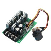
I don’t understand what would be involved in attempting to replace one if the pots in a DC-DC boost converter with a fixed but switched resistance, but doing so with one of these PWM motor controllers looks trivial since the potentiometer is already connected by wires and even a connector:

E86264BE-FC6A-4998-A88C-C51BEDDCD0E9.jpeg


You are focusing on very simple and easy-to-use solutions based on OTS components/technology, which I applaud.

I’m going down the path of trying to find a way to control export power from battery using a ‘smart’ PLC-based energy meter.

The PLC will monitor export power as other members such as GXMNow have pioneered. The remaining ‘gap’ for how the PLC can control the amount of battery power available to a Microinverter comes down to throttling with either a DC-DC converter as you have used or with one of these PWM controllers.

The current ripple from a PWM controller is as bad as it can get, but if there is a way to effectively filter that current ripple from reaching the input capacitors of a Microinverter, the control through duty-cycle looks to be much easier.

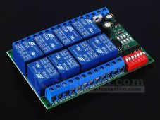
My PLC communicates in Modbus / RS485 and there are low-cost Modbus/RS485-based relay banks available that should make it easy to select one of 16 distinct power / duty-cycle levels (8 relay module pictured):

820F7913-8D28-4F91-8D73-A2E7B2CFFA27.jpeg

Programming a PLC goes way beyond the kind of simple, easy, and foolproof solutions you are looking for but the changing of the rules here in California make the complexity of a ‘smart’ energy meter pretty much mandatory if attempting to export DC-coupled bonus power under an export cap during daylight hours…
 
I have never worked out efficiency, or bothered with it but I have a lot of room for panels and lots of sunlight.
So I just add more panels.
My theory is - the efficiency problem will be sorted by new, cheap, devices coming on.
I will put them in when available.
Totally agree except that power electronics including charge controllers, DCDC converters, PWM controllers and inverters with poor efficiency translate to excessive heat generation and premature failure.

So seeking higher-powered Microinverters so you will avoid saturation and lost solar power, I am 100% with you - that is a fool’s errand, especially if you have space to add more solar panels and mucroinverters.

But if the total-chain solar efficiency loss from battery to AC power is worse than 80%, it’s worth digging into why rather than ignoring it.

My GTILs deliver ~80% efficiency from 24VDC battery to 120VAC power, and I consider that the absolute worst I’m willing to live with. The fans are loud and kick-in often whenever the inverter is running over half-power for more than a few minutes.

My Microinverters have efficiency of 95.5%, so as long as I can find a way to control battery power being delivered at better than 15% efficiency loss on the way, that’s a win.

The DCDC converters apparently deliver efficiency of ~85% but that 15% loss creates the heat that they warn you about beyond 50% of max rating.

These PWM controllers also warn you about excess heat when running beyond 50% of max rating for a sustained period, but they are apparently starting from an efficiency of ~95% rather than 85%…

That’s 1/3rd the heat generation and it’s the reason the higher-powered DCSC-converters have much more serious heatsinks and even integrated fans compared to the PWM controllers.

The lost energy and lost value of that energy is a non-issue, but having a system fail in 3-5 years versus 5-10 or even 10-20 years of is an issue…
 
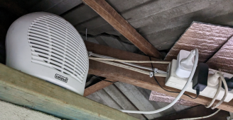
I currently use fan heaters on Wi-Fi timers to burn off excess production.
The one shown is under my carport outside.
Our limit here is 5KW per hour during the day.
I stay under 3KW easily by turning one of those on 10AM-2PM.
I turn on more fan heaters if needed.
Screenshot_20230422-065426.png
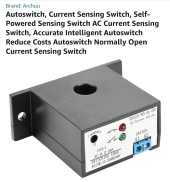
I plan to use 3 CT auto switches.
One each phase provided the first one works.
So the CT can be set to hit a relay, say, 300W 240VAC going to grid.
It then turns on a delay timer, say, 20 mins, this runs the fan heater for, say, 30 minutes and switches off.
It is just a matter of getting the current sense right - it might be 700W setting & time delay, to run fan heater, 120 mins.
Then it is all totally automatic.
If this is successful - I will do the other 2 phases.
.
Screenshot_20230422-070228.png
 
Last edited:
Totally agree except that power electronics including charge controllers, DCDC converters, PWM controllers and inverters with poor efficiency translate to excessive heat generation and premature failure.

So seeking higher-powered Microinverters so you will avoid saturation and lost solar power, I am 100% with you - that is a fool’s errand, especially if you have space to add more solar panels and mucroinverters.

But if the total-chain solar efficiency loss from battery to AC power is worse than 80%, it’s worth digging into why rather than ignoring it.

My GTILs deliver ~80% efficiency from 24VDC battery to 120VAC power, and I consider that the absolute worst I’m willing to live with. The fans are loud and kick-in often whenever the inverter is running over half-power for more than a few minutes.

My Microinverters have efficiency of 95.5%, so as long as I can find a way to control battery power being delivered at better than 15% efficiency loss on the way, that’s a win.

The DCDC converters apparently deliver efficiency of ~85% but that 15% loss creates the heat that they warn you about beyond 50% of max rating.

These PWM controllers also warn you about excess heat when running beyond 50% of max rating for a sustained period, but they are apparently starting from an efficiency of ~95% rather than 85%…

That’s 1/3rd the heat generation and it’s the reason the higher-powered DCSC-converters have much more serious heatsinks and even integrated fans compared to the PWM controllers.

The lost energy and lost value of that energy is a non-issue, but having a system fail in 3-5 years versus 5-10 or even 10-20 years of is an issue…
Good, sound reasoning.
I am benefiting, greatly, already from you & others.
It can only get much better with this work.
 
I currently use fan heaters on Wi-Fi timers to burn off excess production.
The one shown is under my carport outside.
Our limit here is 5KW per hour during the day.
I stay under 3KW easily by turning one of those on 10AM-2PM.
I turn on more fan heaters if needed.
View attachment 145896
I plan to use 3 CT auto switches.
One each phase provided the first one works.
So the CT can be set to hit a relay, say, 300W 240VAC going to grid.
It then turns on a delay timer, say, 20 mins, this runs the fan heater for, say, 30 minutes and switches off.
It is just a matter of getting the current sense right - it might be 700W setting & time delay, to run fan heater, 120 mins.
Then it is all totally automatic.
If this is successful - I will do the other 2 phases.
.
View attachment 145897
That had been my precise plan until exchanges with GXMNow convinced me to plunge into the world of PLCs.

The other concern I had with current sensors is that they don’t actually calculate watts and that can mean leaving a great deal of potential export on the table (at least around here).

Grid voltage is almost 240VAC or even slightly below in the morning and often (but not always) increases to over 250VAC by midday.

The highest I’ve ever witnessed so far was about 254VAC.

The conservative thing to do is to set your current limit at Export Limit / Highest Possible Grid Voltage (255VAC in my case) but that means any time grid voltage is low, you’ll be throttling as much as 6% before you needed to…

Then when I saw how much a proper energy meter costs, trying to cobble together my own with a PLC and bit of programming seemed like a good investment.

But yeah, monitoring export current with a current sensor wired to activate a relay for some pre-determined interval (to avoid thrashing) is the far simpler solution…
 
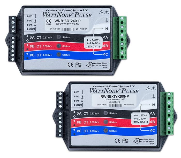
WattNode?

$250 ~ $370, and I see $100 on eBay.


Yeah, WattNode is pretty much the Gold Standard, but a PLC-based energy meter can do everything it can do plus slot more for half the non-eBay price…

Plus, while a CT current switch can directly control a relay, with a WattNode you still have sone interfacing / screwing around to deal with…
 
That had been my precise plan until exchanges with GXMNow convinced me to plunge into the world of PLCs.

The other concern I had with current sensors is that they don’t actually calculate watts and that can mean leaving a great deal of potential export on the table (at least around here).

Grid voltage is almost 240VAC or even slightly below in the morning and often (but not always) increases to over 250VAC by midday.

The highest I’ve ever witnessed so far was about 254VAC.

The conservative thing to do is to set your current limit at Export Limit / Highest Possible Grid Voltage (255VAC in my case) but that means any time grid voltage is low, you’ll be throttling as much as 6% before you needed to…

Then when I saw how much a proper energy meter costs, trying to cobble together my own with a PLC and bit of programming seemed like a good investment.

But yeah, monitoring export current with a current sensor wired to activate a relay for some pre-determined interval (to avoid thrashing) is the far simpler solution…
Gee. I maybe I should stick to what I have got.
I may just do one CT on the busiest phase.
Just gives me another option.
What are KW export are you limited to?
So far this year I have exported 1900KW
 
Last edited:
Yeah, WattNode is pretty much the Gold Standard, but a PLC-based energy meter can do everything it can do plus slot more for half the non-eBay price…

Plus, while a CT current switch can directly control a relay, with a WattNode you still have sone interfacing / screwing around to deal with…
I will have to read up on these.....Thanks.
 
That had been my precise plan until exchanges with GXMNow convinced me to plunge into the world of PLCs.

The other concern I had with current sensors is that they don’t actually calculate watts and that can mean leaving a great deal of potential export on the table (at least around here).

Grid voltage is almost 240VAC or even slightly below in the morning and often (but not always) increases to over 250VAC by midday.

The highest I’ve ever witnessed so far was about 254VAC.

The conservative thing to do is to set your current limit at Export Limit / Highest Possible Grid Voltage (255VAC in my case) but that means any time grid voltage is low, you’ll be throttling as much as 6% before you needed to…

Then when I saw how much a proper energy meter costs, trying to cobble together my own with a PLC and bit of programming seemed like a good investment.

But yeah, monitoring export current with a current sensor wired to activate a relay for some pre-determined interval (to avoid thrashing) is the far simpler solution…

Funnily enough, this is where I started before looking at microinverters and storage.

I have built an Arduino based energy monitor and logger based on the info at openenergy.org to log my house use and solar production. This then expanded into switching on WiFi sockets when I have excess solar, and next into diverting excess into my immersion heater using the principles explained by Robin emley in his MK2 PV diverter .

I still have excess solar on sunny days which is why I'm interested in getting an inverter controllable, I can switch on chargers when it's sunny using my controller, then use the inverter to fill in the gaps and overnight use. The aim is to have the inverter producing just enough to cover my use but not feed back to grid. I already have the power monitoring sorted so closed loop control is easy enough, I just need to get this inverter controllable through the pwm unit!

The Arduino controller is cheap to do as you just need a CT coil, Arduino Uno and a AC transformer for the power measurement and you can add any control code you like, but it's not really an off the shelf solution..
 
Gee. I maybe I should stick to what I have got.
I may just do one CT on the busiest phase.
Just gives me another option.
What are KW export are you limited to?
I should stay under 3.5kW but there is an ‘under no circumstances will export exceed 105%’ clause meaning the absolute limit is probably closer to 3675W…
So far this year I have exported 1900KW
Is that just from your bonus system or all solar including grid-tied.

My 1.14kW DC-coupled bonus array generates 1750kWh of DC energy, most of which gets stored in my battery and using my GTIL inverters, that 1750kWh of DC gets converted to 1400kWh of AC…

My 4kW grid-tied array generates 5100kWh annually, so the DC-coupled bonus power amounts to +27%…
 
Funnily enough, this is where I started before looking at microinverters and storage.

I have built an Arduino based energy monitor and logger based on the info at openenergy.org to log my house use and solar production. This then expanded into switching on WiFi sockets when I have excess solar, and next into diverting excess into my immersion heater using the principles explained by Robin emley in his MK2 PV diverter .

I still have excess solar on sunny days which is why I'm interested in getting an inverter controllable, I can switch on chargers when it's sunny using my controller, then use the inverter to fill in the gaps and overnight use. The aim is to have the inverter producing just enough to cover my use but not feed back to grid. I already have the power monitoring sorted so closed loop control is easy enough, I just need to get this inverter controllable through the pwm unit!

The Arduino controller is cheap to do as you just need a CT coil, Arduino Uno and a AC transformer for the power measurement and you can add any control code you like, but it's not really an off the shelf solution..
Where are you based and are you just trying to cut back on your electrical bill or do you have grid-tied solar (officially)?

I’ll probably end up trying an Arduino or RPi before the dust settles but the equivalent of a blue screen event made me nervous relying on an OS-based platform for anything critical. PLCs are much more limited but should be more bullet-proof for mission-critical control.

But a backup controller is a good idea in any case…
 
Funnily enough, this is where I started before looking at microinverters and storage.

I have built an Arduino based energy monitor and logger based on the info at openenergy.org to log my house use and solar production. This then expanded into switching on WiFi sockets when I have excess solar, and next into diverting excess into my immersion heater using the principles explained by Robin emley in his MK2 PV diverter .

I still have excess solar on sunny days which is why I'm interested in getting an inverter controllable, I can switch on chargers when it's sunny using my controller, then use the inverter to fill in the gaps and overnight use. The aim is to have the inverter producing just enough to cover my use but not feed back to grid. I already have the power monitoring sorted so closed loop control is easy enough, I just need to get this inverter controllable through the pwm unit!

The Arduino controller is cheap to do as you just need a CT coil, Arduino Uno and a AC transformer for the power measurement and you can add any control code you like, but it's not really an off the shelf solution..
Great insights.
 
I should stay under 3.5kW but there is an ‘under no circumstances will export exceed 105%’ clause meaning the absolute limit is probably closer to 3675W…

Is that just from your bonus system or all solar including grid-tied.

My 1.14kW DC-coupled bonus array generates 1750kWh of DC energy, most of which gets stored in my battery and using my GTIL inverters, that 1750kWh of DC gets converted to 1400kWh of AC…

My 4kW grid-tied array generates 5100kWh annually, so the DC-coupled bonus power amounts to +27%…
We get no bonus here at all.
Part of this is battery energy this year
About 14kw per day.
All my electricity is 240v AC.
I don't understand the bonus power at all.
I have produced 6300kw, so far, this year.
(1568kw from battery)
Last year 12,100kw all up.
( About1400kw from battery)
 
We get no bonus here at all.
Part of this is battery energy this year
About 14kw per day.
All my electricity is 240v AC.
I don't understand the bonus power at all.
I have produced 6300kw, so far, this year.
(1568kw from battery)
Last year 12,100kw all up.
( About1400kw from battery)
Oh, all I mean by ‘bonus’ is they I have an official 4kW grid-tied array which exports all power net of load/consumption to grid.

I set up a small 1kW DC-coupled array charging a battery initially for backup power but then realized that using GTIL inverters, I could use that ‘bonus’ energy to offset load, hence increasing export.

So all J mean by ‘bonus’ is that this is added solar energy intended primarily to offset consumption through battery storage and time-shift.
 
Where are you based and are you just trying to cut back on your electrical bill or do you have grid-tied solar (officially)?

I’ll probably end up trying an Arduino or RPi before the dust settles but the equivalent of a blue screen event made me nervous relying on an OS-based platform for anything critical. PLCs are much more limited but should be more bullet-proof for mission-critical control.

But a backup controller is a good idea in any case…
I'm UK based, I do have an officially installed solar system that came with the house when I bought it. It's on an old/good generation tariff where there is a separate meter and I get paid on everything generated regardless if I use it or not. But it does mean I can't modify the system or tap off DC power.
Basically I want to do AC storage so I can reduce my bill and use everything I generate..

Arduino isn't really os based, it's much more like a plc but more codeable. And I'm probably going to do a hardware watchdog to shut everything down if the controller freezes...
 
Oh, all I mean by ‘bonus’ is they I have an official 4kW grid-tied array which exports all power net of load/consumption to grid.

I set up a small 1kW DC-coupled array charging a battery initially for backup power but then realized that using GTIL inverters, I could use that ‘bonus’ energy to offset load, hence increasing export.

So all J mean by ‘bonus’ is that this is added solar energy intended primarily to offset consumption through battery storage and time-shift.
OK. I get it.
I get US .047 credit for each KW
Anyone putting in solar now get US .007
1/7th the amount.
 
Back
Top