diy solar

diy solar

Video explaining my problem with my install

Still scratching my head why he measured 9V at the inverter but 53V at the battery. Had the breaker tripped the battery display would be off. Breakers are slow to react to inrush current unlike a fuse.

The BMS is solid state so will have minor leakage voltage when “off” due to inrush. Again one would assume the voltage measured at both the inverter and battery display would match, unless of course there is a voltage drop in the cable which has now been excluded.

If the battery current is insufficient, again the voltage readings should match. Its gotta be a clue…
 
Last edited:
Still scratching my head why he measured 9V at the inverter but 53V at the battery. Had the breaker tripped the battery display would be off. Breakers are slow to react to inrush current unlike a fuse.

The two BMS's are solid state so will have minor leakage voltage when “off” due to inrush. Again one would assume the voltage measured at both the inverter and battery display would match, unless of course there is a voltage drop in the cable which has now been excluded.

If the battery current is insufficient, again the voltage readings should match. Its gotta be a clue…
The voltages are different because the BMS is shutting down after the CAPS have incrementally charged. It is not giving enough energy to charge the CAPS all at once. By switching on and off it is slowly charging caps until they are full then the unit works as it should. I say BMS but the breaker could also be at issue but since it does not trip on its own I don't think that is the problem.
 
Still don't get it but that's just my simple mind.

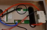
Does the 90-degree bend in the negative cable at the BMS look suspicious?

BMS.jpg
 
IT IS NOT THE MPP it is most likely the BMS try and bypass it.
@ghostwriter66 maybe next time you can hold my beer.

There are two failsafes in that battery and no, i do not recommend bypassing ANYTHING with NMC cells!! DO NOT TRY AT THOME!

If that bettery is rated at 65 amps and the breaker is rated at 63 amps, I do not recommend going over that. It is one of the two that is protecting the battery if not both. Bypassing these failsafes can lead to bad things but maybe not for a short time as the caps charging but I'd rather see a differnent test like the 4 car batteries than bypassing the breaker or BMS with these fragile cells.
 
first class of my first year of EE school the professor said - always check the cables -- and its 95% of the time a cable or connector -- don't tell anyone how you fixed it - just have them think of you as a brilliant engineer .... BUT for the other 5% of the time it's not a cable or connection - the next 4 years we will be teaching you trouble shooting and design
Buckle up everyone, we have a 5%er problem!
 
There are two failsafes in that battery and no, i do not recommend bypassing ANYTHING with NMC cells!! DO NOT TRY AT THOME!

If that bettery is rated at 65 amps and the breaker is rated at 63 amps, I do not recommend going over that. It is one of the two that is protecting the battery if not both. Bypassing these failsafes can lead to bad things but maybe not for a short time as the caps charging but I'd rather see a differnent test like the 4 car batteries than bypassing the breaker or BMS with these fragile cells.
Dont get me wrong I am not suggesting bypassing the BMS permanently. I was just hoping for a test. The specs of the battery say 130 amps the BMS says 60 AMPS probably allows for some sort of surge current. All I am saying which is what you are saying is it is most likely not a problem with the MPP.
 
Cable looks partially broken to me.
I didn't notice that but if it was partially broken or had smaller capacity, it would not be going to 0 volts on the output, it would be showing a different symptom. You can use 10 guage wire here and you would have the same problem. I would actually bet that if you can go down to 16 guage, the wires will get hot during the initial power up but it would limit the current enough to bring up the inverter.. That is the issue we are having.

I.E. Temp fix to this issue would be a buck/boost inverter that lowers the voltage from the battery 1v and limits to output to 60 amps. This would charge the caps a little slower and limit the surge to the capacity of the batteries. Then, this will work to the batteries max capibility.

The only real solution is to get a second battery for 120Amp surge capacity or just go LiFePo4 for the long haul.. And that you can take to the bank. :cool:
 
Dont get me wrong I am not suggesting bypassing the BMS permanently. I was just hoping for a test. The specs of the battery say 130 amps the BMS says 60 AMPS probably allows for some sort of surge current. All I am saying which is what you are saying is it is most likely not a problem with the MPP.
I agree and for a quick test, it probably won't hurt anything but it still has to be noted that it is a dangerious proposition to remove failsafes in a battery even for a few milliseconds. I'm not going to recommend it because I don't want to be responsible for the battery bulge.. Then again, as long as the OP knows to not keep it that way, don't apply a load to the MPP and just test for startup of the MPP to prove he needs a second battery, then it might be OK.
 
Dont get me wrong I am not suggesting bypassing the BMS permanently. I was just hoping for a test. The specs of the battery say 130 amps the BMS says 60 AMPS probably allows for some sort of surge current. All I am saying which is what you are saying is it is most likely not a problem with the MPP.

Looks like OP is going to demend recompence from the vender.
He paid a lot of money, things don't work and now he's pissed in the American sense.
Just about time to start getting pissed here in the Canadian sense.
 
Still scratching my head why he measured 9V at the inverter but 53V at the battery. Had the breaker tripped the battery display would be off. Breakers are slow to react to inrush current unlike a fuse.

The BMS is solid state so will have minor leakage voltage when “off” due to inrush. Again one would assume the voltage measured at both the inverter and battery display would match, unless of course there is a voltage drop in the cable which has now been excluded.

If the battery current is insufficient, again the voltage readings should match. Its gotta be a clue…

That voltage with no load could just be residual from the MMP or the BMS after cutoff.. It also could be leakage from the MOSFET transisters in protection mode so you are actually seeing Base->Collector bias voltage with very little current. It's really 0v if it was loaded and should be considered 0v.

Look at the wriring in the battery picture. The voltage display is shown from the switch side of the 63 amp breaker and the battery side of the BMS. This is why the display shows different than the output.. the output is on the other side of the BMS. If you moved the black wire that is soldered to the large blue wire on the BMS to the large black wire on the BMS, the display would show the actual output voltage. Now it is showing the 'before BMS' voltage.
 
I see the video is back to switch flipping and no voltage measures... fine... I'm going to unsubscribe! ;)

So the current theory is the inrush demands from the capacitor are causing the battery to fault, which is why cycling it with the power switch works.
From what Craig said above, it sounds like a defective battery (e.g., inrush is 60 Amps, battery can supply 130 amps) since the MPP works fine once it has started.

If this is the case, easy way to fix it is to put a resistor (e.g., high wattage DC light bulb) in the path temporarily while the caps charge up. When the light goes out you can release the switch (e.g., no current flow as the caps are charged). It's a gentler way to charge those caps too, so perhaps not so temporary?
1593275114599.png

BTW, it could never have been that the gauge is to small ... electricity doesn't work that way.... if the gauge was to small it's not that it wouldn't work, it's that the wires would heat up to where the insulation melted off or caught fire.
 
Last edited:
I see the video is back to switch flipping and no voltage measures... fine... I'm going to unsubscribe! ;)

So the current theory is the inrush demands from the capacitor are causing the battery to fault, which is why cycling it with the power switch works.
From what Craig said above, it sounds like a defective battery (e.g., inrush is 60 Amps, battery can supply 130 amps) since the MPP works fine once it has started.

If this is the case, easy way to fix it is to put a resistor (e.g., high wattage DC light bulb) in the path temporarily while the caps charge up. When the light goes out you can release the switch (e.g., no current flow as the caps are charged).


BTW, it could never have been that the gauge is to small ... electricity doesn't work that way.... if the gauge was to small it's not that it wouldn't work, it's that the wires would heat up to where the insulation melted off or caught fire.
It's not the current theory it's my theory from 4 days ago lol.
 
Once the caps charge, that step is complete and everything is good. He can keep it that way as long as his load is < 63 amps from the battery. Again, that problem is down the road and it will happen as long as his MAX current is 63-65 amps. This issue is just a warning to what is coming later.
 
@randerson, there is a super-easy way to prove it's the battery not the MPP.

1) With everything connected, flip on the battery switch (DON'T TOUCH THE SWITCH AGAIN! LEAVE IT ON)
2) Disconnect the battery to MPP cable via the Anderson connector.
3) Measure the voltage at the Anderson connector of the battery.

I bet you'll be surprised at what you see.
 
Back
Top