diy solar

diy solar

[FIXED] Careful if you ordered Apexium DIY Box (melted fuse cover)

From Seplos Video at 1:46. This is correct. I would deem Apexium's manual just unreliable entirely at this point.

View attachment 193557
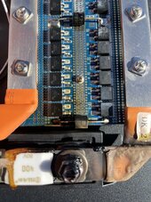
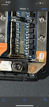
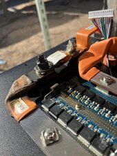
I should add to this statement the it does bend the bus bar slightly, and you can even see if the picture that is quoted, the vertical part (horizontal in the picture actually) is actually bowed, like a rainbow. This isn't ideal, but it technically is a flexible bus bar, and does go together fairly easily.
 
400A fuse on 280Ah battery is not totally pointless as these batteries can sustain over 500A for at least a half minute and thousands of amps momentarily. Of course wiring and BMS should be also rated for 400A in that case.

For temporary fix I’d clean the contact surfaces of the bus bars and fuse with scotchbrite and assemble fuse holder back together(assuming that fuse holder has some structural strenght left), this time without the washers ”The fuse holder seems to have
Thanks for the temp fix idea. Attached some photos, any concerns about the burning of the motherboard? You think bus structure looks good?


My thanks to the OP for an informative Thread. It never hurts to step back and review things to see if they makes sense even if instructed to do something a certain way.
Well mine nearly blew lol

In case this helps anyone, I was getting a CAPA warning and occasionally a SCP warning

IMG_7780.jpegIMG_7779.jpegIMG_7776.jpegIMG_7778.jpegIMG_7777.jpeg
 

Attachments

  • IMG_7782.jpeg
    IMG_7782.jpeg
    247.2 KB · Views: 6
  • IMG_7773.png
    IMG_7773.png
    771.5 KB · Views: 7
  • IMG_7776.jpeg
    IMG_7776.jpeg
    188.2 KB · Views: 8
Thanks for the temp fix idea. Attached some photos, any concerns about the burning of the motherboard? You think bus structure looks good?


Well mine nearly blew lol

In case this helps anyone, I was getting a CAPA warning and occasionally a SCP warning

View attachment 193577View attachment 193578View attachment 193579View attachment 193608View attachment 193609
Are you going to remove the washers? Those pictures still show washers between the fuse and the bussbar.
 
Thanks for the temp fix idea. Attached some photos, any concerns about the burning of the motherboard? You think bus structure looks good?


Well mine nearly blew lol

In case this helps anyone, I was getting a CAPA warning and occasionally a SCP warning

View attachment 193577View attachment 193578View attachment 193579View attachment 193608View attachment 193609

Wow.
The manual instructing those washers to be there is just terrible.
They must go between the fuse holder and the lower bussbar.
 
Wow.
The manual instructing those washers to be there is just terrible.
They must go between the fuse holder and the lower bussbar.
Actually on to of both fuse and busbar ( which should be one top of eachother)
Between fuseholder and fuse there should be a crush ring

This will allow you to put the required 7-10 nm of pressure on top of it
 
Can't believe how they screwed up a good piece of kit that they rebadged and didn't take care of properly creating a none dangerous manual for it..

Just a gentle reminder that we're not playing with Barbies here..
This is high power and will be dangerous If not done correctly
 
Actually on to of both fuse and busbar ( which should be one top of eachother)
Between fuseholder and fuse there should be a crush ring

This will allow you to put the required 7-10 nm of pressure on top of it
If anything less conductive than copper is between fuse and bussbar, resistance will cause heat.
 
there is quite a big difference between the Seplos ( official ) build instruction videos and this apexium manual...

in any case glad i use the Seplos video's .

First thing jumping out at me is they say to put copper washers on each cell terminal, THEN PROCEED TO USE ALUMINUM BUSSBARS BETWEEN CELLS!!!!
Huge issue there...
Copper and aluminum dissimilar metal corrosion can be a problem...
Are the washers nickle plated?
 
First thing jumping out at me is they say to put copper washers on each cell terminal, THEN PROCEED TO USE ALUMINUM BUSSBARS BETWEEN CELLS!!!!
Huge issue there...
Copper and aluminum dissimilar metal corrosion can be a problem...
Are the washers nickle plated?
Those didn't come with my kit. Not sure why.
 
First thing jumping out at me is they say to put copper washers on each cell terminal, THEN PROCEED TO USE ALUMINUM BUSSBARS BETWEEN CELLS!!!!
Huge issue there...
Copper and aluminum dissimilar metal corrosion can be a problem...
Are the washers nickle plated?
They are crush rings of a very soft copper..can easily dent them pushing on them with my nail

And tinned/nickeled
 
Last edited:
I'm quite certain he means for the one labeled "C" in your image to be removed. You want the increased surface area of the contact between the bars, without the added resistance of the washer itself, which is not designed to be an especially good conductor.

Slight difference opinion here, I would move washer C to the bottom below the busbar. Just a little extra space between the fuse and holder. The fuse itself of that type can get pretty warm at high current. Still gets it out of the current path.
 
For the smoke damage to the board I would clean it off with some 99% isopropal alcohol and an acid brush or tooth brush, just in case it is slightly conductive.
 
Back
Top