diy solar

diy solar

20 or 30A breaker for Enphase Combiner receiving 16 M215 Microinverters

SparkyGriswald

New Member
Joined
Sep 23, 2023
Messages
22
Location
Sylvania, OH
I am centerfeeding a string of 16 M215 Enphase Miroinverters (so the junction box is in the middle of 2 sets of 8 MI). Altogether this would be 16 MI that would land on the breaker in the Enphase Combiner box and I am wondering if this should be 20A or 30A.

The current per MI is 0.9 so 16* 0.9 = 14.4 then multiply that by 1.25 (per NEC 690.8(A) = 18 and then multiply again by 1.25 (per NEC 690.8(B) for a total 22.5A

If it at all matters the reason I went with MI is because we have had issues with shading and so my expectation of the 16 to be fully producing is low. But that likely does not matter to an inspector right?
 
According to the Enphase Quick Start Guide. Up to 17 M215 microinverters are allowed on a 20A circuit breaker.
 

Attachments

  • Enphase M250 and M215 Microinverter - Quick Install Guide.pdf
    977.9 KB · Views: 1
I am not aware of an Enphase design that allows over 20A branch circuit. Did you miss the row in the Enphase spec sheet? It’s standard on microinverter spec sheets to say maximum number of micros per branch

The correction factor is 1.25 * current for output after a power conversion (which is generally limited to the nameplate by the circuit design). It is 1.25*1.25 for output from bare solar modules since the only inherent limiting is the strength of the sun

I recommend posting your full design and perhaps paying to get the plans drafted for your permit application.
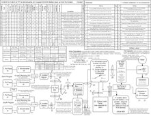
Attached is the latest version after amanedments. The other thread I tagged you in has the original plan. The updated version has the correct Temp ratings and other improvements.
 

Attachments

  • Line Diagram w Conduit -3-3-2024.jpg
    Line Diagram w Conduit -3-3-2024.jpg
    332.2 KB · Views: 3
That now makes more sense to have it limited to 20A breaker based on Manufacturer's specifications and that will protect the 12 AWG of the Q cable (75C rating of 25A 90C rating of 30A but then would need to be Temp derated).

Thanks for helping me think that through.

So in terms of landing the combined branches on the XW Pro Hybrid Inverter - would you then use a 40 A breaker since it is fed by 2 20 Amp breakers? Meaning that the 32* 0.9A per MI * 1.25 * 1.25 (43A) would not apply and rather my original intent (see other thread) of 32* 0.9A per MI * 1.25 (34.6) would apply - meaning use a 40A breaker on the XW pro solar input?
 
So in terms of landing the combined branches on the XW Pro Hybrid Inverter - would you then use a 40 A breaker since it is fed by 2 20 Amp breakers? Meaning that the 32* 0.9A per MI * 1.25 * 1.25 (43A) would not apply and rather my original intent (see other thread) of 32* 0.9A per MI * 1.25 (34.6) would apply - meaning use a 40A breaker on the XW pro solar input?
40A breaker is the most straightforward way to do that. You can technically use a 35A but you anyway will need #8 or bigger wire here.

You will need to stay under the limit of the AC port that you are tying into on the XW Pro.

You need to make sure you have 6.9kW of charging and inverter capacity, factoring in the capability of the XW Pro and your battery. This is the case for any AC coupled inverter.

Regarding the XW Pro Hybrid, do check the threads on that. There are a lot of experience and opinions on its strengths/weaknesses when used to AC couple, and the issues are different for off grid and for on grid. Same applies for any AC coupled setup, they all have their own quirks.

Is M215 UL1741SA with smooth frequency-watts shifting? I believe there is some experience on the forum with using non-FW capable hardware. In that case some people will want to backfeed through a relay protected AC port. But even pre FW inverter is supposed to shutoff when the frequency exceeds bounds (the difference with FW is that it is smoother and 1741SA inverters are more tolerant of glitches)
 
Is M215 UL1741SA with smooth frequency-watts shifting?
Thank you, UL1741 only - no SA. My current understanding is that I will then have sudden shut offs and not be modulated. Am OK with that. Would that be an issue at all with Grid Tie in?

Yes I have seen the posts on the issues. I was able to get Used M215s and used PVs and so that is what lead to this design. Here is one post https://diysolarforum.com/threads/inverter-for-backup-play-nicely-with-m215s.42342/page-3
But it seems that the original poster of that thread is no longer active.
@Ampster I know you were active in that thread If you could take a gander at my plan I would appreciate it. Thanks!
 
Thank you, UL1741 only - no SA. My current understanding is that I will then have sudden shut offs and not be modulated. Am OK with that. Would that be an issue at all with Grid Tie in?
That is fine. Modulation is possibly snake oil anyway as commonly described. To me, the ride-through (more robustness against frequency and voltage glitches) and the faster turn back on is probably more provably impactful. With 1741 shutoff it has to re-qualify grid which is like a 10-20min delay. With 1741SA it can probably be ramped down to 1%

The Grid Tie-In issue is something important actually now that you mention it. A lot of state power authorities don't allow 1741 in new installations because they expect to need the ride-through and throttle back capabilities in the future to stabilize the grid, and they want stuff installed around this time to be future proof. And your microinverters would be considered grid tie.
 
The Grid Tie-In issue is something important actually now that you mention it. A lot of state power authorities don't allow 1741 in new installations because they expect to need the ride-through and throttle back capabilities in the future to stabilize the grid, and they want stuff installed around this time to be future proof. And your microinverters would be considered grid tie.
Thanks, I did ask my local utility if they had issue with it and no comment. So my path currently is to get Inspector approval - then submit plans to the utility for final determination.

Could you expand more on what you mean by "You need to make sure you have 6.9kW of charging and inverter capacity," Thanks.
 
Could you expand more on what you mean by "You need to make sure you have 6.9kW of charging and inverter capacity," Thanks.
Charger side: if loads disappear then charger can ramp up to absorb the excess solar.

Inverter side: if sun disappears then the battery inverter can ramp up to supply the gap.

This is assuming the SoC is within a range capable of accommodating this.

This means that you are not supposed to have loads that are unable to be carried by battery inverter alone. A full Enphase IQ8 system is somewhat more robust in some cases (since they have a battery less backup capability) but less in others.

Dark start is a challenge with all hybrids, probably harder with AC couple. If you are just above the low SoC% cutoff you likely need to turn off most loads to help keep the AC coupling stable. You need to do this anyway with DC but there are more failure modes in AC couple.
 
Would that be an issue at all with Grid Tie in?
None, other than the potential code issue mentioned. When grid is down you are probably not going to see much production unless you can have loads and charge enough to take the production. Otherwise AC coupled inverters will be shut off when the XWPro increases frequency. Or they may never start up unless there is enough load on the XW Pro to lower frequency.
 
If the local grid has low solar participation (whether small scale or large scale) then it is believable that they don't yet care about 1741SA or 1741SB. Those become needed at high % of adoption.
 
If the local grid has low solar participation (whether small scale or large scale) then it is believable that they don't yet care about 1741SA or 1741SB. Those become needed at high % of adoption.
That is SUPER helpful to know as one of the many reasons I am doing this is that there is very few solar installs in the area. Initially I was going to work with a solar cooperative, but that fell through and so that has evolved into this current 6 month odyssey.
How large is a typical packet for permit?
My current packet seems to be obscenely large - I included all the spec sheets for the individual components to show UL listings and other pertinent issues).
I think the two I submitted / reviewed for my house were both around 20 pages. Probably 6-8 pages of actual plans and the rest spec sheets.

Our renewable grid in California (wind + solar) can already supply 100% of demand on some hours of the year (I think same applies to Texas), so having the controls that SA and SB provide to throttle back solar & avoid solar getting knocked offline as 1741 can be are important. Both of those reduce the amount of dispatchable generator capacity needed to stabilize the grid.

I have been worrying this past week about whether some bad actors from overseas will target the SB controls to be naughty 🤷
 
Back
Top