diy solar

diy solar

Aolithium rack battery discharge, equalization

flammafeuer

New Member
Joined
May 25, 2022
Messages
62
I have 2 Aolithium rack batteries, and got my Victron 150/35 connected in and doing some light solar charging, and noticed a couple of things, raising a couple of questions:
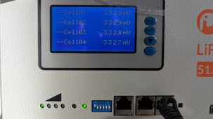
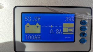
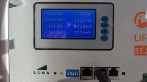
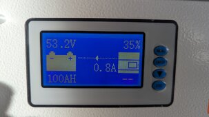
  • Should I expect the batteries to eventually match charge levels? The master/top battery is charging faster than the slave/bottom, and is staying higher (consistently about 3% more charge).
  • I left the system alone for 5 days, without any input power, just the Victron essentially sleeping, and the system lost about 1% power day (~100W) across both batteries. Is that normal?
In the photos, the one with the higher charge % and slightly higher cell voltages is the master.
 

Attachments

  • PXL_20231227_231422366.jpg
    PXL_20231227_231422366.jpg
    211.9 KB · Views: 5
  • PXL_20231227_231528526.jpg
    PXL_20231227_231528526.jpg
    186.1 KB · Views: 5
  • PXL_20231227_231427465.jpg
    PXL_20231227_231427465.jpg
    214.6 KB · Views: 5
  • PXL_20231227_231531909.jpg
    PXL_20231227_231531909.jpg
    179.8 KB · Views: 5
What is your wiring configuration?

Is this using the parallel cables or is it on a buss bar?

Does the victron report the same SOC as the master or the slave or something in between?
 
What is your wiring configuration?

Is this using the parallel cables or is it on a buss bar?

Does the victron report the same SOC as the master or the slave or something in between?
I have the batteries in parallel with the parallel cables. The documentation mentions a bus bar, but I frankly can't understand the chingrish manual well in that regard, and I think it is about what is connecting the cells inside. I don't have any communication going to the Victron charge controller, and frankly don't know how to do that (yet), so The Victron isn't reporting

I'm not sure which part of the wiring configuration you're interested in, but the master's battery positive goes out to a T class fuse, then a busbar. The 150/35 is connected through an MBRF fuse to the same bus bar. The solar panels are connected through an inline fuse to a disconnect to the 150/35. I haven't yet connected in my DC-DC converter or the inverter.
 
Ok a few things,

We should confirm the master-slave addressing is correct. I will check the manual but I think you have it right.

Communications should be Victron CAN-BUS I believe but you will need to make a custom cat5e network cable.. Or find someone who can. The network cable that comes with the packs seems to br useless since they have no PC monitoring software. The pinouts on the battery are known so all that is needed are thr pinouts for the victron to match the can-high and can-low signals.. Then set the correct protocol with dips 5 and 6.

I was mostly asking if you had the inverter connection cables attached to the master pack only or if one is attached to the master and the other attached to the second pack.

Good luck.
I'm pretty sure I have a network cable crimper somewhere. That said, the bluetooth SmartSolar 150/35 just seems to have the VE.direct plugin (which I do not have), and I don't see a network cable jack.

I just in the past 30 minutes wired in the inverter, which is a WZRELB 3kW (not the wall mount, just the standard) with a wired remote. It also doesn't have other communication that I can see (except the wired remote).

Do you have recommendations on what accessories/components would make this "smarter"?
 
oh I am not too familiar with that gear so perhaps communications is not required or feasible.

As long as the positive and negative leads connecting to the inverter are not attached to the same battery pack it should be able to share the current properly. With the parallel cables just make sure the inverter does not take more than 125A continuous as the 25mm2 cables are maxed at that point.

Other than that, once you have both packs charged to 100% they should reset the SOC at the similar time and be pretty close..
 
Back
Top