diy solar

diy solar

Circuit Schematic for an Aims 4000watt/48 volt split phase low frequency inverter/charger

Roger Dale

New Member
Joined
Jan 9, 2024
Messages
8
Location
Columbus Ohio
Can anyone help me out with this? I have searched for hours trying to find a circuit schematic for this Aims split phase inverter with no luck. In the manual that came with the inverter there is only one schematic for a single phase but that is a completely different animal . I did find one for a Sigineer split phase and am led to believe that Aims and Sigineer are the same thing but I need to be sure. Aims tech support has been useless. I need the schematic because I think I have wired something wrong and if I had it I could figure it out. Can anyone help me? Loads of thanks.
 
What leads you to believe something is wired wrong? There is + and - in from the battery and for split phase there is L1, L2 and Neutral. There could be a ground but the inverter would work for testing purposes without it connected to anything.
How is it wired now?
 
What leads you to believe something is wired wrong? There is + and - in from the battery and for split phase there is L1, L2 and Neutral. There could be a ground but the inverter would work for testing purposes without it connected to anything.
How is it wired now?
I didn't say in my first post but my system is an off grid system using grid power as backup. Remember this is split phase. The Aims specs say input from grid power is L1 L2 and earth ground. Output which runs to an AC distribution panel is L1 L2 and neutral. The problem is this. The Sigineer schematic I mentioned shows the input earth ground, regardless of whether the inverter is in AC mode or battery mode, connected to absolutely nothing. And as far as I can figure it isn't needed for anything where it is connected. What I need to do is remove this earth ground wire and connect it to the neutral bus bar in the AC distribution panel so I'll have a neutral/ ground bond. That way if there is a ground fault or short when the inverter is in AC mode the double pole breaker in the grid distribution panel will trip and when in battery mode the breaker for the circuit the fault is on will trip in the PV power distribution panel. What I have just stated will only work IF... the input earth ground wire actually is useless. THAT IS THE QUESTION. Here is a link to the Sigineer schematic; www.sigineer.com/features/sigineer-power-split-phase-inverter-schematics- ac-mode-battery-mode/
 
The Aims specs say input from grid power is L1 L2 and earth ground. Output which runs to an AC distribution panel is L1 L2 and neutral.
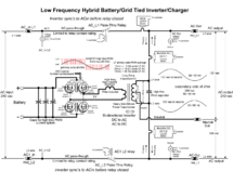
Yes, the diagram @RCin FLA posted shows exactly how this works. The Neutral is derived from the transformer (secondary side) of the LF inverter.
The problem is this. The Sigineer schematic I mentioned shows the input earth ground connected to nothing.
Earth ground should be connected to the inverter enclosure only. There should NOT be continuity between the output neutral and the case of the inverter. There SHOULD be continuity between the Input Ground terminal and the inverter enclosure.

Earth ground should NOT be connected directly to the Neutral bus in the panel because the neutral bus may be insulated from the panel enclosure which is supposed to have an earth ground also. In a normal situation, the ground bus and neutral bus are separate. Ground buss is attached to the breaker panel enclosure and Neutral is insulated from it. If a N-G bond is needed, a wire or strap is added so the 2 bus bars are tied together.
 
Last edited:
Yes, the diagram @RCin FLA posted shows exactly how this works. The Neutral is derived from the transformer (secondary side) of the LF inverter.

Earth ground should be connected to the inverter enclosure only. There should NOT be continuity between the output neutral and the case of the inverter. There SHOULD be continuity between the Input Ground terminal and the inverter enclosure.

Earth ground should NOT be connected directly to the Neutral bus in the panel because the neutral bus may be insulated from the panel enclosure which is supposed to have an earth ground also. In a normal situation, the ground bus and neutral bus are separate. Ground buss is attached to the breaker panel enclosure and Neutral is insulated from it. If a N-G bond is needed, a wire or strap is added so the 2 bus bars are tied together.
Would you please clarify something for me? You mention inverter enclosure and the case of the inverter. Are they not the same thing? If not, how are they different?
 
This type of inverter has a small issue.

The transformer in the inverter does produce the neutral while it is running off grid. When off grid, the neutral should be ground bonded. But any time you are connected to the grid on the input, this ground bond needs to be lifted. Inverters from Schneider and Victron (and probably others as well) have a relay that connects the neutral as needed depending on the operating mode.

If this is in a camper, boat, or other mobile system with a shore power connection, you should get a transfer switch box that does the proper neutral ground bonding. Even if you only connect the L1/L2 to a 240 volt split phase shore power connection, you still need to lift the neutral to ground bond from this inverter output. Any imbalance between the L1 and L2 on either the grid side or the transformer in the inverter will cause the neutral tap of the transformer to NOT be at proper ground zero volt potential.

In my Schneider XW-Pro 6,800 watt inverter, the output transformer neutral center tap is left floating when the system is running on grid. The inverter is essentially only pushing out 240 volt floating AC current. The grid transformer is then supplying the neutral. If the system switches off grid, it disconnects the L1 and L2 inputs, and then connects the transformer center tap to the neutral buss to provide the proper 120/0/120 split phase AC output.

Since this inverter appears to lack this neutral disconnect relay, you need to be very careful how you run your ground bonding.
 
Just a power path schematic/block dia
Just a power path schematic/block diagram.

View attachment 192312
The Aims users manual I have shows input as L1 L2 and bear copper ground. Output is L1 L2 and neutral as shown in the schematic you provided (neutral being created from the center tap of the secondary transformer coil). However your schematic does not show the input ground wire and what it is connected to. I wouldn't think it was for a chassie ground because there already is a grounding lug on the battery input side of the inverter. What is this ground, where is it connected and what does it do?
 
Back
Top