You are using an out of date browser. It may not display this or other websites correctly.
You should upgrade or use an alternative browser.
You should upgrade or use an alternative browser.
DC Circuit Breaker for Hybrid Inverter
- Thread starter hgg
- Start date
SolaroSsaurius
New Member
- Joined
- Aug 27, 2022
- Messages
- 171
Hi.You'd do well to notice these symbols on your switchgear:
They are important to identify what equipment is rated for what purpose.
Note: Not all switches are rated to break load current and not all circuit breakers provide adequate isolation.
View attachment 115262
I'm trying to learn as much as possible regarding DC load protection.
I didn't understand your remarks regarding the symbols and this switch. Where is the marking?
Does this means it cannot be used in a 24v LiFePO4 system under load? (max 160A in my case)
Thanks in advance!
SolaroSsaurius
New Member
- Joined
- Aug 27, 2022
- Messages
- 171
DammHi.
I'm trying to learn as much as possible regarding DC load protection.
I didn't understand your remarks regarding the symbols and this switch. Where is the marking?
Does this means it cannot be used in a 24v LiFePO4 system under load? (max 160A in my case)
Thanks in advance!
Just noticed hgg's remarks regarding the manual!
Dah...
SolaroSsaurius
New Member
- Joined
- Aug 27, 2022
- Messages
- 171
,Hi.It could be used as a disconnect under low/no load IF it didn't have an unacceptable voltage drop, (...)
Could you please point me to where the voltage drop in this switch is mentioned?
(I'm reading this in my mobile, I probably missed it)
Thanks
meetyg
Solar Addict
- Joined
- Jun 4, 2021
- Messages
- 1,124
After having many doubts about this issue and ordering some supposedly non-polarized DC breakers from Aliexpress, I ended up getting this:
While it's still from a Chinese manufacturer, it's sold on the Renogy store on Amazon and specifically says that it's non-polarized. No strange polarity or line/load markings on it either.
Yes, it's expensive but I decided to go safe for my AIO inverter and battery bank. I will also have a fuse on the battery anyways.
OzSolar
Whatever you did, that's what you planned.
What's wrong with the F series from Carling? Too pricey? Odd mounting? I don't believe they are directional and are rated to break the load.


Hedges
I See Electromagnetic Fields!
- Joined
- Mar 28, 2020
- Messages
- 21,035
I think this is the model Midnight sells (175A & 250A)
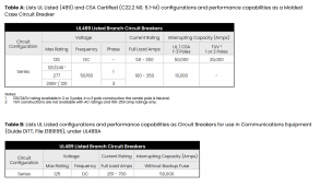
"Maximum Voltage 125VDC, 277VAC"
We agonize over DC voltages that exceed breaker rating during charging conditions (especially for a nominal 48V battery.)
Ability to interrupt arc, and at what current, is our greatest concern there.
In the case of this Carling breaker, I think "Maximum ... 277VAC" means the highest nominal voltage.
You could use the breaker in a 120Vrms circuit, or European 220Vrms, or 277Vrms277/480Y (each pole sees 277V to neutral.)
But line tolerance means that could be 277Vrms +/- 5%.
If you had a 480V line to line fault or overload, the ganged breaker poles would all trip and voltage would be interrupted by two poles in series.
Correction:
277 is shown only for 1 pole.
120Vrms per pole for 2 or 3 poles. Only 10,000 AIC for AC, vs. 50,000 AIC for DC.
(Surprising the interrupting capability is lower for AC. My guess would be it could interrupt as much as for DC, but they tested and listed to meet a standard application requirement for branch circuits. Main breaker for commercial applications might require 100kA or 200kA.)

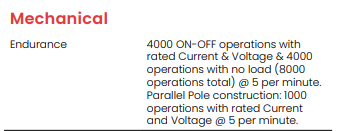
Interesting the "Mechanical Endurance" has different ratings for Parallel Pole construction. 1000 operations at rated current rather than 4000 operations.
Is that because arc is interrupted more by one pole than another, perhaps due to it opening sooner?
Or mechanical stress of one pole causing others to switch?
Or, the pole opens more slowly because held back by other poles?
At rated current (not over), the 1000 operations would be mechanically performed, not caused by internal trip mechanism.
I like that they spec resistance. 100A breaker is < 0.0007 ohms.
I had problems with Squared-D QO270 breakers having higher resistance, which caused parallel paths to share unequally.
That was thermal-magnetic, so a resistance element; These Carling are magnetic-hydraulic.
The spec (as written) doesn't appear to derate AIC for multiple parallel DC poles (only number of cycles.)
I could probably use on a battery bank feeding a pair or three inverters, good for split-phase or 3-phase.
In the case of a DC fault, it would be only one pole interrupting short-circuit current. But if opening was slowed by dragging the other two levels behind it, might actually reduce its AIC. Best to clarify with manufacturer rather than relying on spec as written! Needs to be supported by actual test conditions. Individual poles rather than ganged would definitely be supported as spec'd.
"Maximum Voltage 125VDC, 277VAC"
We agonize over DC voltages that exceed breaker rating during charging conditions (especially for a nominal 48V battery.)
Ability to interrupt arc, and at what current, is our greatest concern there.
In the case of this Carling breaker, I think "Maximum ... 277VAC" means the highest nominal voltage.
You could use the breaker in a 120Vrms circuit, or European 220Vrms, or 277Vrms
But line tolerance means that could be 277Vrms +/- 5%.
Correction:
277 is shown only for 1 pole.
120Vrms per pole for 2 or 3 poles. Only 10,000 AIC for AC, vs. 50,000 AIC for DC.
(Surprising the interrupting capability is lower for AC. My guess would be it could interrupt as much as for DC, but they tested and listed to meet a standard application requirement for branch circuits. Main breaker for commercial applications might require 100kA or 200kA.)

Interesting the "Mechanical Endurance" has different ratings for Parallel Pole construction. 1000 operations at rated current rather than 4000 operations.
Is that because arc is interrupted more by one pole than another, perhaps due to it opening sooner?
Or mechanical stress of one pole causing others to switch?
Or, the pole opens more slowly because held back by other poles?
At rated current (not over), the 1000 operations would be mechanically performed, not caused by internal trip mechanism.
I like that they spec resistance. 100A breaker is < 0.0007 ohms.
I had problems with Squared-D QO270 breakers having higher resistance, which caused parallel paths to share unequally.
That was thermal-magnetic, so a resistance element; These Carling are magnetic-hydraulic.
The spec (as written) doesn't appear to derate AIC for multiple parallel DC poles (only number of cycles.)
I could probably use on a battery bank feeding a pair or three inverters, good for split-phase or 3-phase.
In the case of a DC fault, it would be only one pole interrupting short-circuit current. But if opening was slowed by dragging the other two levels behind it, might actually reduce its AIC. Best to clarify with manufacturer rather than relying on spec as written! Needs to be supported by actual test conditions. Individual poles rather than ganged would definitely be supported as spec'd.
OzSolar
Whatever you did, that's what you planned.
They are.I think this is the model Midnight sells (175A & 250A)
Thanks for applying your keen eye.
As long I've been around this stuff those breakers have been the standard that tier one OEMs shipped with the DC power centers. Of course that was long before the AIC needed for today's Lithium batteries was a major issue. The only problem I've had with them is that their handles are stunningly easy to break off. Under normal circumstances not a problem but during installs or when moving equipment just one bump and "bye-bye"
Hedges
I See Electromagnetic Fields!
- Joined
- Mar 28, 2020
- Messages
- 21,035
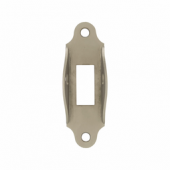
Something like this, but of suitable dimensions.

 www.frostelectric.com
I broke the handle off a QO230, just operating it by hand. Plan to see if their lifetime warranty is honored (I have a few with various failures.)

Cooper 7949 | Frost Supply
Cooper 7949 Metal Toggle Switch Lever Guard Lockable (Arrow-Hart) Residential Grade, Eaton
I broke the handle off a QO230, just operating it by hand. Plan to see if their lifetime warranty is honored (I have a few with various failures.)
OzSolar
Whatever you did, that's what you planned.
Nice. I've got buddy with 3D printer that is always wanting to make me something.Something like this, but of suitable dimensions.
View attachment 119531
Cooper 7949 | Frost Supply
Cooper 7949 Metal Toggle Switch Lever Guard Lockable (Arrow-Hart) Residential Grade, Eatonwww.frostelectric.com
I broke the handle off a QO230, just operating it by hand. Plan to see if their lifetime warranty is honored (I have a few with various failures.)
Other than small terminals they seem to fit the bill. Carling Technologies 125A DC 2-Pole on eBay.
I'll relate my experience...
Would you share the brand and the model?
I bought sample MCBs from China also with the same non-polarized description, but also with the same + and - markings.
Would you share the brand and the model?
I just tested the Tomzn TOB1Z-125 with 18A current at 36V. No issues in disconnecting the load in both directions. It also does not have any markings stating which direction should the current go. It has a magnet. But it seems to be non-polarized.
The only specs I'm able to find are for the TOB1Z-63. The trip type is thermal magnetic. The 125A version is almost two times wider, so there is no guarantee that it is also thermal magnetic, but for sure - there is a magnet inside. The 63A version has 6kA breaking capacity and the 125A version has 10kA breaking capacity. Seems pretty adequate for a battery mechanical power switch.
The only specs I'm able to find are for the TOB1Z-63. The trip type is thermal magnetic. The 125A version is almost two times wider, so there is no guarantee that it is also thermal magnetic, but for sure - there is a magnet inside. The 63A version has 6kA breaking capacity and the 125A version has 10kA breaking capacity. Seems pretty adequate for a battery mechanical power switch.
Last edited:
Hedges
I See Electromagnetic Fields!
- Joined
- Mar 28, 2020
- Messages
- 21,035
"Thermal Magnetic" doesn't mean it has a magnet, although it may.
A coil of wire which fast trips the breaker under severe overload is why it is "magnetic" operating.
If a breaker contains a permanent magnet, AFAIK it is polarized. If it worked both ways that would be because voltage and current were relatively low.
These things will work fine as a switch under low or no load. Ability to interrupt full voltage and current, and overload, are the questions.
Got some more clarifications - the 63A and below are polarized. The ones above 63A are non-polarized. This may be the reason why there are twice as big as the ones that are for up to 63A.
I'm kind of confident that the TOB1Z-125 is going to do the job. Moreover - I'm not expecting this to be a failsafe. It will be used as a manual switch for disconnecting the battery when performing maintenance (like checking for loose busbars or adding another battery).
I'm kind of confident that the TOB1Z-125 is going to do the job. Moreover - I'm not expecting this to be a failsafe. It will be used as a manual switch for disconnecting the battery when performing maintenance (like checking for loose busbars or adding another battery).
Sorry gents, I have missed this lively discussion for a while.
The MCBs I tested were from a company called YRO.
I tested them actually to trip for overcurrent conditions, and they don't have any magnetic attractions or repulsions.
Other than that, I have no affiliations and make no guarantees as to their continued quality.

 yrdq.en.alibaba.com
.
The MCBs I tested were from a company called YRO.
I tested them actually to trip for overcurrent conditions, and they don't have any magnetic attractions or repulsions.
Other than that, I have no affiliations and make no guarantees as to their continued quality.

Yueqing Yirui Electric Appliance Co., Ltd. - Surge Protective Device, Circuit Breaker
Yueqing Yirui Electric Appliance Co., Ltd., Experts in Manufacturing and Exporting Surge Protective Device, Circuit Breaker and 0 more Products.
Many of MIdnite solar's breakers are non-polarized. http://www.midnitesolar.com/pdfs/breakers_11x17.jpg
DC Circuit Breaker for Hybrid Inverter
Question with thanks Is the circuit breaker Aelifv C125 A 1000 V correct to put between the battery system 24 v and the inverter 3500 w?Hedges
I See Electromagnetic Fields!
- Joined
- Mar 28, 2020
- Messages
- 21,035
3500W/24V = 146A, so a 125A breaker would trip well below full load.
1000V is much higher than needed.
What is expected inverter efficiency? 90%?
3500W/24V/0.90 x 1.25 margin x 1.12 ripple factor = 227A is my recommended minimum breaker.
Here's a 250A 125V DC breaker:
1000V is much higher than needed.
What is expected inverter efficiency? 90%?
3500W/24V/0.90 x 1.25 margin x 1.12 ripple factor = 227A is my recommended minimum breaker.
Here's a 250A 125V DC breaker:
Similar threads
- Replies
- 4
- Views
- 242
- Replies
- 1
- Views
- 158
- Replies
- 1
- Views
- 267
- Replies
- 16
- Views
- 632
- Replies
- 2
- Views
- 183


