I bought a couple Ecoflow Delta 2 power banks (1024wh each w/1800w inverters) back in November 2023 along with a pair of 220w bifacial panels to use while camping. I was so impressed with them that my curiosity piqued and I started to think about building my own, higher capacity unit. I purchased and read Will Prowse's book as well as "Off-Grid Solar Power Simplified," and Badhra & Holmes' "Off-Grid Solar Power" in addition to picking up a couple books on wiring. I watched numerous YouTube videos on the designing a system as well. That's the extent of my experience with electrical. Naively, I set about to purchase the components I thought I'd need for a DIY build.
Problem is I have a cognitive impairment caused by a medical trauma years ago, and as a result, I have trouble sequencing information (if-then statements, tax form instructions, etc.) especially when only presented verbally. I'm usually OK with visual information if I can reduce the visual field and concentrate on one area. But, zooming out again and trying to see how that piece fits the overall puzzle can be difficult for me. You can imagine how branching circuits can be confounding to me. As I age, my CRS also seems to be getting worse. But, I'm to the point where I think I have purchased all that I need (I think) and am ready to finalize the plan and physical layout.
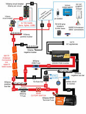
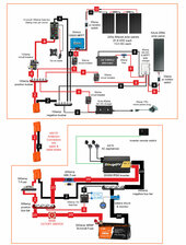
The build involves: a 12v 230ah LiFePO4 battery; a 12v 2000w psw inverter; Victron 100|50 MPPT charger, Redodo 12v 40amp DC-DC/MPPT and 14.4v 40amp AC-DC chargers; wires, fuses, AC plugs and sockets; fans; other 12v lights/sockets and USB outlets. I plan to have the battery, shunt, inverter and a couple related AC outlets in a lower (wheeled) modular toolbox and the chargers and most everything else housed in an upper toolbox with SB175 Anderson connectors linking the toolboxes.
In the lower box I have 2/0 cables linking the inverter, battery, 300amp bus bars, fuses, and shunt with smaller wires (2, 4 & 6awg), fuses, 150amp bus bars, and 50-60amp breakers and fuses in the upper box. I decided to use a 300amp MRBF terminal fuse on the battery with 300amp bus bars and a 300amp ANM fuse in the circuit to the positive inverter connection. 2awg is planned for the SB175 connectors between the boxes with smaller wires, breakers, and fuses linking things in the upper box.
I also planned to use a 300amp T-fuse somewhere in the positive line near the battery but I'm wondering now if that is redundant given the MRBF terminal fuse? So, I placed it after the main cutoff switch leading to the positive bus bar and close to the SB175 Anderson link. Figured that couldn't hurt. Would it be better placed elsewhere?
I would appreciate other eyes looking at my preliminary drawing and offering suggestions, corrections, or support. Thanks.
Joe
p.s., FWIW, I already made a couple errors in purchasing stuff. The Redodo DC-DC charger really can't handle the pv expansion I had in mind but I'm OK with it since I can still employ it as a charger from the vehicle electrical system when driving or to split a small pv circuit from my van roof to the 230ah battery. Likewise, the T-fuse might not be needed. And, I probably could have used Anderson SB120 connectors instead of the larger SB175 ones, but I see that oversight as one of economy rather than utility.
Problem is I have a cognitive impairment caused by a medical trauma years ago, and as a result, I have trouble sequencing information (if-then statements, tax form instructions, etc.) especially when only presented verbally. I'm usually OK with visual information if I can reduce the visual field and concentrate on one area. But, zooming out again and trying to see how that piece fits the overall puzzle can be difficult for me. You can imagine how branching circuits can be confounding to me. As I age, my CRS also seems to be getting worse. But, I'm to the point where I think I have purchased all that I need (I think) and am ready to finalize the plan and physical layout.
The build involves: a 12v 230ah LiFePO4 battery; a 12v 2000w psw inverter; Victron 100|50 MPPT charger, Redodo 12v 40amp DC-DC/MPPT and 14.4v 40amp AC-DC chargers; wires, fuses, AC plugs and sockets; fans; other 12v lights/sockets and USB outlets. I plan to have the battery, shunt, inverter and a couple related AC outlets in a lower (wheeled) modular toolbox and the chargers and most everything else housed in an upper toolbox with SB175 Anderson connectors linking the toolboxes.
In the lower box I have 2/0 cables linking the inverter, battery, 300amp bus bars, fuses, and shunt with smaller wires (2, 4 & 6awg), fuses, 150amp bus bars, and 50-60amp breakers and fuses in the upper box. I decided to use a 300amp MRBF terminal fuse on the battery with 300amp bus bars and a 300amp ANM fuse in the circuit to the positive inverter connection. 2awg is planned for the SB175 connectors between the boxes with smaller wires, breakers, and fuses linking things in the upper box.
I also planned to use a 300amp T-fuse somewhere in the positive line near the battery but I'm wondering now if that is redundant given the MRBF terminal fuse? So, I placed it after the main cutoff switch leading to the positive bus bar and close to the SB175 Anderson link. Figured that couldn't hurt. Would it be better placed elsewhere?
I would appreciate other eyes looking at my preliminary drawing and offering suggestions, corrections, or support. Thanks.
Joe
p.s., FWIW, I already made a couple errors in purchasing stuff. The Redodo DC-DC charger really can't handle the pv expansion I had in mind but I'm OK with it since I can still employ it as a charger from the vehicle electrical system when driving or to split a small pv circuit from my van roof to the 230ah battery. Likewise, the T-fuse might not be needed. And, I probably could have used Anderson SB120 connectors instead of the larger SB175 ones, but I see that oversight as one of economy rather than utility.