boboxx
New Member
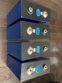
I just received my 4x Lifepo4 280Ah Batteries for the camper. After looking around I opted to try my luck with Dongguan Billion Electronic Technology. I was dealing with Wilson who was ok do deal with. I was given may excuses after I had placed the order to get an initial tracking number only to realized if was for a different order. Finally after 2 weeks of waiting the correct tracking number was sent. he kept blaming the logistic company. The order took about just under 4 weeks to arrive.
The cost per cell was 72$ (288$ total) and 220$ for shippint to Canada via UPS. Duty and brokerage was 55$ CAN
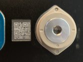
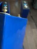
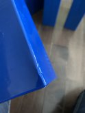
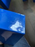
The cells where packaged poorly, each cell was individually wrapped in cardboard boxed (no padding) in and then placed in a lager box with bubble wrap padding. These where sold as "New EVE Cell A grade" but EV dosen't list a 280Ah cell. Looking at the cell it's hard to believe they are A grade as they have quite a few dents and pucks. Another stage thing is that cell sounds like flooded cells when turning them sideways.
Cell Voltage / Impedance
Cell A: 3.2879v / 0.19mΩ
Cell B: 3.2925v / 0.19mΩ
Cell C: 3.2927v / 0.19mΩ
Cell D: 3.2921v / 0.18mΩ
I'm still missing my BMS so I can't do much more with the cells as of yet, but I just tought I would share with you. I have no affiliation with Wilson or that company but I would not recommend dealing with that company.
The cost per cell was 72$ (288$ total) and 220$ for shippint to Canada via UPS. Duty and brokerage was 55$ CAN
The cells where packaged poorly, each cell was individually wrapped in cardboard boxed (no padding) in and then placed in a lager box with bubble wrap padding. These where sold as "New EVE Cell A grade" but EV dosen't list a 280Ah cell. Looking at the cell it's hard to believe they are A grade as they have quite a few dents and pucks. Another stage thing is that cell sounds like flooded cells when turning them sideways.
Cell Voltage / Impedance
Cell A: 3.2879v / 0.19mΩ
Cell B: 3.2925v / 0.19mΩ
Cell C: 3.2927v / 0.19mΩ
Cell D: 3.2921v / 0.18mΩ
I'm still missing my BMS so I can't do much more with the cells as of yet, but I just tought I would share with you. I have no affiliation with Wilson or that company but I would not recommend dealing with that company.
Attachments
Last edited:
")