diy solar

diy solar

Input needed for electrical layout

tmorrgold

New Member
Joined
Oct 13, 2019
Messages
45
I am in the process of converting my truck to an RV/tiny home and have no background in electrical. My son-in-law is an electrician and helping me out with everything, but he doesn't have experience with DC systems. So we have the whole truck wired up, and now are ready to set up the battery, inverter and solar panels.

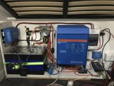
Here is how I think things go together.

I don't know how to make schematics on the computer, so hope this is comprehensible. Thanks!!

1573235588474.jpeg
 
Can you post the model number of the epever CC and the specs of the solar panels, or link to the web site for solar panels? Checking that the CC and panel voltage will be compatible.
 
The Epever is 50A/150V Tracer AN and panels are 320w/40voc/10amps each connected in series.
 
OK then, you've done your homework on that one :) The wiring diagram looks OK to me, but just in case see if anyone else has something to say before proceeding.
 
Looks good if wires are sized appropriately. Very nice to see a battery protect connected to the step down converter.
 
I am running into some confusion in determining wire sizes.

For example, the (green) run from my battery bank to DC converter/fuse block is about 6' one way.

My battery bank is 24v/120amps.

When I input these numbers into the wire size calculator on wirebarn.com, it says 6 gauge wire. Am I doing that right?

But when I look at the NEC table for wire ampacity, it says the max current for 6 gauge thhn wire is only 75 amps, and I would need 2 gauge wire for 120 amps.

Also, when I calculate wire size for the run to my water tank heater pad (35' one-way run for 7 amps, 12v), it says to use 6 gauge wire. That just seems too big to me, esp. when the pad itself comes with 3' of 14 gauge wire to connect with.
 
You'd need to think about the maximum current you will be drawing over the wire and the distances involved. You might have a 120ah battery but if you only run a 5 watt LED lamp off it the wire to the lamp can be fairly high gauge because there is little current involved. However if you plan on putting the light 500 metres from the battery for some bizarre reason, you have to use a heavier gauge to account for the resistance of the wire over that long distance causing excessive voltage drop at the far end.

Your CC is rated at 50 amps, the PV array can produce enough electricity to result in approx 40 amps into the battery so your wire between the CC and the battery needs to be rated for at least 40 amps, preferably more, and if the run is more than a couple of metres, IMO, an lower gauge needs to be used to avoid excess drop. The CC needs to have a good view of the voltage at the battery terminals to determine state of charge and to ensure proper charging. If the wire between the CC and battery is not heavy enough there could be a volt or more difference between what is measured at the battery terminals and what the CC sees on it's terminals.
 
Ok, so that's 7 amps at nominal 12 volts, approx 84 watts. Now we think about the cable distance, 35' or 10 meters.

What's an acceptable power loss over that cable? Let's say 5 watts leaving us with about 80 watts of heat from the pad. This reduction in heating capability is a judgement call that you have to decide on. There are quite a few factors to consider about how this power loss happens, but for simplicity we will just ignore it all and assume everything is purely linear resistive loads.

The allowable resistance for the 10 metres of wire with 5 watts of loss calculates to about 0.5 ohms. So now we can look up a AWG copper wire chart and see that 10 metres of 12 AWG wire will have a resistance of about 0.5 ohms but that's for one wire alone. We have two wires, + and - to the heat pad so we have to halve the resistance in each wire so instead of 12 AWG we now want 7 AWG.

Their recommendation of 6AWG is spot on.
 
Back
Top