Steve_S
Offgrid Cabineer, N.E. Ontario, Canada
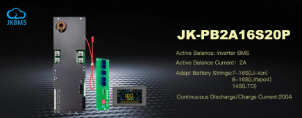
With that style of JK, they are using dual wires which is quite common and completely ok, these Silicone jacketed wires can indeed carry the load and do so quite well. I have pushed things to the edges during the Thrash Test cycle where I pushed everything to the edge, including the BMS. Pushing in 200A through a single BMS only resulted in slightly warm wires as did drawing 200A both for an extended period (30 minutes each way). You are overthinking it....
As an FYI, my setup, the dual 7AWG wires from BMS are connected to 4AWG Silicone Wire. No "hot" spot on Butt connecter or terminals either (where you'd expect) everything was equally warm as it should be.
BTW: The New JK Inverter BMS comes with Dual Connectors and you pick your own wires. The game is changing up & fast.


