diy solar

diy solar

REVIEW MY SCEMATIC AND TELL ME WHAT I HAVE WRONG

WHI13tan

New Member
Joined
Feb 10, 2024
Messages
10
Location
idaho
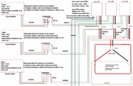
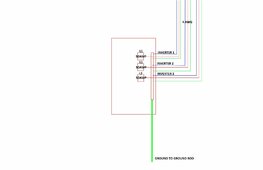
I have attached a sketch of my system schematic. I do not have this system built yet but it shows all the inverters, batteries, and panels I currently have. My biggest challenge I have is determining the right wire size from the inverters to the battery bank. When I am running the calculations, I don't know if I should use the continuous output rating or the max peak power rating. Each inverter is rated at 5000w output with a 10000w peak output. 125A max battery discharge and 100a max charge rate. If each inverter is rated at 100a does that mean I could theoretically put 300a into the battery at one time? Not that I would need to charge with that much current at this time but it just a future thought of being rated to do so and how to size the wire accordingly. Also feel free to critique any of my breakers or basically anything else as nothing is locked in stone yet.

This is what I currently have sized.

Inverter to buss bar-125A max discharge rate x 1.25 = 156amps
10ft of cable at 156a calls for 2/0 wire.

Buss bar to battery (THIS IS WHERE I AM LOST ON WIRE SIZING)
15000W total between three inverters-15000w/48v=312a x 1.25 = 390a
I cannot find a wire that would allow for this type of amperage at least in the calculators I am finding. What size do I use or am I calculating wrong? I understand that I will not be pulling or should not be pulling all 15000w at one time but I figure theoretically that's what you calc for. Running the wire size calc i have to drop all the way to 230 amps for it to show that 4/0 is acceptable.
system schematic.jpgsystem schematic 02.jpg
 
4/0 Class M Welding cable rated 405A at 90 deg C

Or run two 2/0 carefully matched lengths in parallel (yuck).
Or go up to 250 MCM if you have a really long run.

And for your own safety put a 350A or 400A class T fuse near the batteries.
And make sure your bus bars are rated 600A or more.
 
Last edited:
Three inverters, each gets its own wire.

Do you have a single battery? Can it source 390A continuous?

"48V, 700 Ah".
0.5C discharge is doable.

Are those single cells, or several in parallel?
I have 405 Ah 6V AGM batteries, 1x 4/0 cable connecting them.
If I used 1200 Ah 2V batteries, those have 2x connections so I would use 2x 4/0 cables, one to each terminal.

You can use multiple cables or busbar(s) as required.
Skip the busbar entirely?
I would consider stack of 3 ring terminals on single battery terminal (if single string), going to 3x fuses or breakers and on to inverters.
At other end of string, I'd stack the ring terminals in other order.

I have 2x 4/0 cables fanned out to 2x fuses, and from there fan out to 4x inverters.
 
I did a quick read of the sparse powmr 5k. I do see a port for parallel operation, but nothing about three-phase support.
Are you sure it supports this mode?
Perhaps Setting #29, but it is not clear.


Split phase ok
 
its for 120/240 split phase. One inverter will power one leg and two inverters the other leg.
OK that’s good, your drawing is correct.

Now how will the powmr 5k know that two of them are on L1 and only one on L2?
does it explicitly support the unbalanced configuration?
 
I did a quick read of the sparse powmr 5k. I do see a port for parallel operation, but nothing about three-phase support.
Are you sure it supports this mode?
Perhaps Setting #29, but it is not clear.


Split phase ok
yes they have a setting and a wiring diagram for 120/240 split phase with three units.
 
4/0 Class M Welding cable rated 405A at 90 deg C

Or run two 2/0 carefully matched lengths in parallel (yuck).
Or go up to 250 MCM if you have a really long run.

And for your own safety put a 350A or 400A class T fuse near the batteries.
And make sure your bus bars are rated 600A or more.
Goes above my knowledge but the page for the wire says 405amps at 600v wonder if it matters that it's for 48v? What's the difference between a t fuse and a 2p dc breaker?
 
Three inverters, each gets its own wire.

Do you have a single battery? Can it source 390A continuous?

"48V, 700 Ah".
0.5C discharge is doable.

Are those single cells, or several in parallel?
I have 405 Ah 6V AGM batteries, 1x 4/0 cable connecting them.
If I used 1200 Ah 2V batteries, those have 2x connections so I would use 2x 4/0 cables, one to each terminal.

You can use multiple cables or busbar(s) as required.
Skip the busbar entirely?
I would consider stack of 3 ring terminals on single battery terminal (if single string), going to 3x fuses or breakers and on to inverters.
At other end of string, I'd stack the ring terminals in other order.

I have 2x 4/0 cables fanned out to 2x fuses, and from there fan out to 4x inverters.
are you saying three inverters each with its own wire to the positive and negative post of the battery to eliminate the buss bar?

yes its a single battery and no at the moment pulling max amps 300+ would probably work but not be good for it at all. More so looking at future sizing. Should the breaker from buss bar to battery be rated with a small safety factor above the max discharge rate to protect it from too high of a discharge rate?

Theoretical max discharge rate should be a c6 rate so roughly 125ah.

these are two 24v wired in series to 48v. may pull it apart to make one 48v so I don't have to use two packs.

guess I could run three wires from each inverter to the battery it just seems like running them to the buss bar then buss bar to battery would be easier, but I guess not.

do you have a picture of your wiring setup where you fan the wires out?
 
600v means maximum voltage, it is a standard electrical class of system (some cables are only 300v rated).

Class T: do a search in the forum for Class T, also check the resources, this is a frequent topic.
Lots of us do not fully trust DC breakers. The fuse is protection against the big BOOM and fire.
10-4 will do thank you,
 
are you saying three inverters each with its own wire to the positive and negative post of the battery to eliminate the buss bar?

Could stack 3 ring terminals and not have a busbar (others here will say not to stack more than two.
Could put a short busbar on the terminal and 3 separate cables bolt to it.
Could fan out 2x cables to short busbar.

yes its a single battery and no at the moment pulling max amps 300+ would probably work but not be good for it at all. More so looking at future sizing. Should the breaker from buss bar to battery be rated with a small safety factor above the max discharge rate to protect it from too high of a discharge rate?

Theoretical max discharge rate should be a c6 rate so roughly 125ah.

Are you saying max discharge rate from battery is only supposed to be 125A?
I think you said 3x 125A for 375A total from battery.

Lead-acid or lithium?

If lead-acid, considering Peukert, how long can battery sustain 375A?
That may be short enough that this isn't "continuous current", so 1x 4/0 could be sufficient.
That's what I did with 4x inverters, figure 500A draw from 405 Ah battery, using 1x 4/0. If my battery was bigger I'd stack 2x 4/0 on every terminal, or two parallel strings (or 2 terminals per string.)

these are two 24v wired in series to 48v. may pull it apart to make one 48v so I don't have to use two packs.

Lithium then? Does BMS support 48V operation? (when it disconnects, FETs or relay sees 48V)

guess I could run three wires from each inverter to the battery it just seems like running them to the buss bar then buss bar to battery would be easier, but I guess not.

For another setup, I'm running cables to fuse holder with multiple cable lug. Or lug with multiple fuses.

do you have a picture of your wiring setup where you fan the wires out?

The two black cables go to one positive battery terminal:

 
Back
Top