


liftbikerun
New Member
HARDWARE INSTALL BELOW, SOFTWARE/FIRMWARE SETTINGS WILL BE UPDATED SOON
The What and Why?:
The goal of this tutorial is to walk you through replacing the blade motor ESCs when they fail. During the process of researching this I found that it isn't just LiFePO4 upgrades that cause this issue, it's happened to quite a few Ryobi owners on stock setups.
**Important notes before beginning**
- You cannot replace only one of the original ESCs, they work as a Master/Slave and require each other to turn on. If either of them are damaged or missing, they will not activate the motors.
- The blade protection will no longer work. IE: You don't have to be seated to turn on the blades.
- The button that slows the blades down no longer functions (I bet I could easily figure this out with an additional pull down resistor to give the impression of say 60% throttle.
- The stock battery gauge no longer functions
During the replacement of my stock lead acid batteries (This started me down the rabbit hole for replacing my lead acid batteries), upon plugging in the new LiFePO4 battery and turning on the machine the Slave ESC decided to give up the ghost and blew up.
It sparked, it smoked, it died.
I hadn't even turned the blades on yet, so it was the initial inrush of current that blew the ESC.

The stock ESCs are quite expensive and can be hard to come by. The cost to replace both the Master and Slave blade motor ESCs can be above $800 (US). After upgrading my batteries to a new LiFePO4, I wasn't in the mood to spend another $800+ on parts that are a known weak point and could/would fail again.
The upgrade path I chose to begin was a cheap set of AliExpress 75100 VESCs. I knew going in these could, and likely would fail. I wasn't prepared for how quickly they failed but I got what I needed out of them; proof of concept. So far, my initial investment into fixing my blown stock ESC is ~$90. Upon installation I was able to figure out the wiring, retainment of the stock blade pto switch, and confirm that the blades could indeed be controlled independently from the stock setup and the mower would continue to work correctly otherwise.
Let's jump in....
The Terminology:
(Borrowed from Google)
VESC -
A VESC, which can stand for either Vedder Electronic Speed Controller or Variable Electronic Speed Controller, is a versatile and programmable electronic device used to control the speed and direction of electric motors. It goes beyond a simple on/off switch by offering precise and dynamic control over various parameters, making it valuable in diverse applications.
Pull-down Resistor -
In the world of electronics, a pull-down resistor plays a crucial role in ensuring predictable behavior for digital circuits. Here's the breakdown:
What it does:
- Prevents "floating" state: When nothing is connected to a logic pin and the circuit is powered on, the pin's voltage level becomes uncertain, known as "floating." This ambiguity can cause unpredictable circuit behavior.
- Defines a default state: The pull-down resistor "pulls" the voltage level of the pin down to ground (logical 0) by default. This ensures a known starting point for the circuit.
- Provides stability: When a switch or sensor connected to the pin opens, the resistor maintains the logical 0 state, preventing misinterpretations caused by the floating state.
What's Needed?
Some of the following can be edit/changed for different things, but this is what I used and I can only attest to it working with these parts.
Tools:
- Ratchet Set to disassemble plastics
- Soldering Gun + Solder
- Tap and Die set - For mounting the VESCs (this is not required)
- Laptop/Computer to run VESC Tool to program Firmware
- 2 - Flipsky 75100 Pro VESCs - https://flipsky.net/products/flipsk...ric-skateboard-scooter-ebike-speed-controller
- 20 AWG Wire - https://www.amazon.com/dp/B089CFST2X
- Wire Shrink Tubing
- 1 - 10k Ohm Resistor
- Wire Terminals w/crimper
- XT90S Connectors to power the VESCs (Repurposed from stock ESCs)
- 3 Phase Wire connector to blade motors (Repurposed from stock ESCs)
Where To Begin?
Disassembly -
Luckily this is one of the easier machines I've ever disassembled. It only requires a handful of screws to be removed and the panels come off pretty easily.
- The side panel is needed to get to the wiring
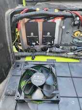
- The motor controllers (both the blade, and the wheels) are located behind here. The bulk of the work is done here.
- The metal deck cover has 4 screws that need to be removed so you can gain access to the wires and motors. I imagine this isn't absolutely required, but it makes the job exponentially easier with this out of the way.
- The control panel has 4 bolts, two of which need to be removed for panel #1 to be removed.

With these removed, you'll have access to everything you'll need to work on this project.
Wiring and Soldering -
The first real step in the process is finding the wires we need to use for our installation.
- Power
- You’ll need to either procure a set of XT90S connectors for the power input for each VESC or you can use the old ones from the faulty ESCs we are replacing (this is what I did).
- Output to Motors
- You’ll also need to either procure connectors that will work with the blade motor connectors or reuse the set from each ESC we are replacing (this is what I did).
- COMMs Connection (Throttle) -
- The Flipsky 75100 Pro VESC has multiple input/outputs but the only ones we care about are #6 which is COMMS and #5 which is our USB connection to our computer to program it.

Additionally, will only need three wires out of the COMMS connector, ADC1 (this is our Analog to Digital Converter), 3.3V, and GND.
This is basically our “throttle”, in this case, we are reusing our PTO switch that is either ON or OFF. This is also why we need our pulldown resistor, as the ADC1 input is not a digital 1 or 0, we need to “pull down” the voltage to 0 with our 10k Ohm resistor. When we do that our VESC sees we have a true “zero” input or zero throttle (off). I found that the ADC1 line carries a voltage that sits almost exactly halfway between 0 and 3.3v which means without the pulldown resister as soon as you turn on the mower the blades would begin moving at half speed.
When we are done, when you pull up on the PTO switch, we will be connecting our 3.3v input to our ADC1 line telling the VESC that we are providing full throttle which will turn the motors on.
- Pick either of the VESCs Ground Wires here, we only need to use one (I used the right most VESC which is mounted in the location of the "Master" ESC we are replacing. Solder the GND wire to one side of the 10k Ohm resistor.
- Take BOTH ADC1 wires and solder the wires to the other side of the resistor while additionally adding a 24” pigtail which will connect to one input of our PTO switch (you’ll want to crimp a 12-10 Yellow female spade connector onto this).
- Heat-shrink around the pull-down resistor we just created.
- Take your 3.3v wire (We only need to use one, again I used the 3.3v of the right most VESC), add an additional 24” to it and solder the joints. Add a 12-10 Yellow female spade connector to this. You’ll be connecting this to the other side of the PTO switch.
******The reason we only need to use one ground, and one 3.3v is the only wire that is unique to each VESC is the ADV1 input. The 3.3v and GND are common and are really only used here as the trigger to tell the VESC that either we have zero input, or full throttle****
- You now have a 24" lead from the ADC1 side of our pull-down resistor, and a 24" lead from our 3.3v. The PTO switch has 2 different inputs, a double spade, and a triple spade. Use the double spade and plug them in on each side (it doesn't matter)

Attachments
Last edited:

