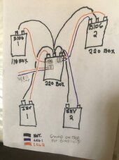
As I said, I'm not an electrician, nor do I even pretend to be, but I do have my Macgyver's license, and have been off grid for over 30 years.
This is my first experience running two inverters to obtain 220V, mostly to run my well pump, and maybe some machinery in building #2 someday.
Building #1 is a small home that doesn't draw a whole lot of energy, maybe 6amps at most if both the small chest freezer, and 100lb ice machine are running at the same time. Most of the lighting is LED and relatively minimal for a 700 sq ft space.
Building #2 is a workshop with LED lighting and a number of machines, of which only 1 ever runs at a time. So with two 6500W inverters, I only ever show using between 6-10% load, maybe a bit more when the well pump is running.
Did you ever do something believing you knew what you were doing, then later thought, wait, did I even do this right?
WEll, that's me right now.
Please review for me. Thank you!
(Sorry for the crap schematic, with these stupid arthritic fingers I'm lucky to even be able to hold a pen.)


