diy solar

diy solar

Solar array not performing to rated power (not even half)

I definitely do not think this is normal. To me there might be a connection issue. Panel wiring. charge controller damaged. solar panel damaged.

Any chance you can try some different panels? try a different charge controller?

how close are the panels to the charge controller?
 
I definitely do not think this is normal. To me there might be a connection issue. Panel wiring. charge controller damaged. solar panel damaged.

Any chance you can try some different panels? try a different charge controller?

how close are the panels to the charge controller?
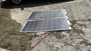
I actually do have some other panels and a small charge controller. I had them running for the day to supplement my power and it running slightly better now because of the position of the sun and the fact that one is being shaded now. Earlier it was out performed by its big brother.
 

Attachments

  • 11813358-5F3A-4FF5-8A0B-519021107CB5.jpeg
    11813358-5F3A-4FF5-8A0B-519021107CB5.jpeg
    1 MB · Views: 14
  • 83E00007-848D-4681-8577-1217E6E9B1BF.jpeg
    83E00007-848D-4681-8577-1217E6E9B1BF.jpeg
    60.8 KB · Views: 14
  • EFA5DB78-E625-40F8-8FAB-02EC2585B3EB.jpeg
    EFA5DB78-E625-40F8-8FAB-02EC2585B3EB.jpeg
    317 KB · Views: 16
I actually do have some other panels and a small charge controller. I had them running for the day to supplement my power and it running slightly better now because of the position of the sun and the fact that one is being shaded now. Earlier it was out performed by its big brother.
My suggestion is to try the other solar panels on the victron charge controller.

Otherwise maybe try 2s2p with your current setup.

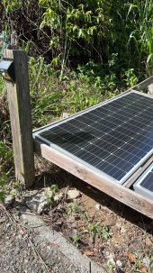
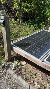
Definitely remove that shading!! haha
 
So here is the update, the panels are operating correctly. The voltage at the panels is between 80 and 95V in the sun. And the voltage inside is 37v. So the issue is my wire. I am going to run a temp wire to see what I get. I am wondering if my mc4 connection is bad. Will update you guys in a few.

UPDATE: ran new wire and got the same results as before. Rule out the wire which is a BougeRV 70 Feet 10AWG Solar Extension Cable. The voltage is high as it should be when the when the charge controller is off. Once I switch the charge controller on the voltage drops to 37-40v. Any idea. ?
Might be the mppt finding the voltage that produces the most watts.
 
since they are all in series, one panel being shaded effects them all.

One thing you could do is remove the panel which is shaded. hook the other three up in series and see what your output is. However removing that post/moving the rack further will allow all 4 panels to function.
 
Last edited:
Might be the mppt finding the voltage that produces the most watts.
You might be into something here. Because my peak voltage when I was on 12v 3 weeks ago I was getting higher voltages.

I am really thinking that it’s because it’s using 24v.
 

Attachments

  • IMG_9750.png
    IMG_9750.png
    295.3 KB · Views: 5
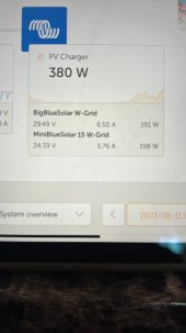
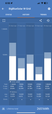
it still looks like you are only getting 350 watts max. is this an improvement?

Did you do anything about the shading?
The shading is out of my control for now and it happens from around 2pm. I use to get 450 - 475w on average. Today I saw about 400w for a moment. I remember getting 625w when they were brand new in 2019. So this has me baffled. FYI in the same position.
 
Measure the OC volts and the SC current of each of the panels. If this is not possible connect two of the panels in series to the controller and evaluate. Experiment with all panel combinations, two from 4.
I suspect resistive volt drops somewhere , in the panel, connections, cable. The tropical climate can be cruel to electrics
Open the housing on the back on the panel and examine. Test the diodes.
You measured expected volts OC. The Victron reported maximum volts 60 to 70 volts.

Regarding charge volts, reduce the absorbtion to 28.4 volts and float to 27 volts, there is a possibility that BMS high cell volts protection tion is occurring.

Mike
 
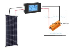
What i would do first is to check each panel independently with a 2ohm resistor capable of handling the 175w the panel can produce at peak irradiance. Use a cheap dc watt meter from amazon, they are like 20 bucks. With this you can absolutely determine if the problem is in one of the panels or in the rest of the system.
test.jpg
 
What i would do first is to check each panel independently with a 2ohm resistor capable of handling the 175w the panel can produce at peak irradiance. Use a cheap dc watt meter from amazon, they are like 20 bucks. With this you can absolutely determine if the problem is in one of the panels or in the rest of the system.
View attachment 162481
This sounds like a fun project to test the panels. What should happen if I connect everything like in the diagram above in the distilled water? Also should this me done in full sun light.
 
You need to remove all the residue after applying; the company makes a specific version for electrical contacts but even that gets mixed reviews.
I use DEOXIT contact cleaner and anti fretting lubricant.
 
Yes they are all factory installed. I even wired the PV connection directly to the charge controller to rule out the breaker same result. Any one running panels on a 24v system, let me know if this is normal.
I had problems with BougeRV MC4 connectors. Cheap metal did not stay lock in the plastic housing. The metal pins were pushed half way down the barrel. Made some contact but not enough for full amperage.
 
This sounds like a fun project to test the panels. What should happen if I connect everything like in the diagram above in the distilled water? Also should this me done in full sun light.
If you do this what will happen is that the solar panel will produce power that goes in the resistor. The watt meter will tell you voltage, current and most important, how many watts the panel is producing.
2 Ohms is what would be required for this panel to produce maximum power at peak irradiance according to the label in the back you showed in the picture. You cand find these yellow 200w resistors everywhere, 2 ohms is a very common one.
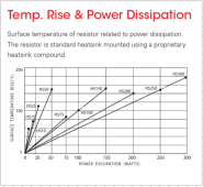
Unfortunately that 200w rating of the resistor is bs. It will take 200w if you attach it to a very good heat sink, which would be a project in on itself. The alternative is submerge it on distilled water, that will keep it cool and is cheap and easy to do. Distilled water doesnt conduct electricity at these voltages.
 
Unfortunately that 200w rating of the resistor is bs. It will take 200w if you attach it to a very good heat sink, which would be a project in on itself.

True of almost all electronic components.
Data sheet often says what they can handle in free air, and if case is held at 25 degrees C. With a derating curve.
Given thermal resistance of your solution you can engineer a design.
Some parts have overly optimistic specs, which you only find by studying curves. But good manufacturers document things well enough.
 
True of almost all electronic components.
I didnt knew that. In case of these resistors i found out the hard way when i saw the 100w ones start smoking at 50w.
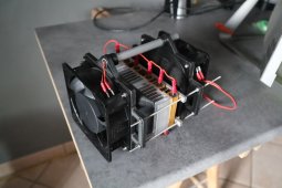
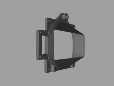
I used this concept to test up to 600w panels when i was making the solar project for my property, 6x100w resistors in parallel required a heat sink and 2 fans to keep them at 120° C when dissipating 600w. I never finished this thing but it worked fineresistors.jpgresistorholder.jpg
 
RTFM.


Data sheet link broken, but here's another copy


"Heat dissipation:
Whilst the use of proprietary heat sinks with lower thermal resistances is acceptable, uprating is not recommended. For maximum heat transfer it is recommended that a heat sink compound be applied between the resistor base and heat sink chassis mounting surface. It is essential that the maximum hot spot temperature of 200°C is not exceeded, therefore, the resistor must be mounted on a heat sink of correct thermal resistance for the power being dissipated."

1692023166935.png
 
Back
Top