diy solar

diy solar

Solar Diagram for small RV

Auskay

New Member
Joined
Jul 27, 2023
Messages
5
Location
Australia
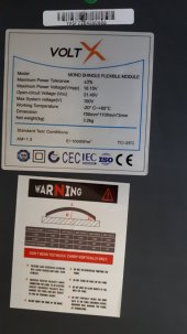
Hi guys, I'm looking for help with solar diagram for my small RV. I have already installed 2x solar panels, one is 100 watts and the other is 160watts. I have 100Amp lithium battery and 1000watts Renogy pure sine wave inverter. I have also universal battery monitor with shunt. I think I have all cables and just now waiting for small fuse box with negative buss bar. Also have 100A circuit breaker. I have to admit I never build any solar system and just now studying all about that. I would be very grateful if anybody can help me with drawing of diagram for my system.
 
Hi I have MPPT 30Amp it is some Chinese no brand from ebay. Also the battery monitor is no brand universal with 300Amp shunt.
 
Hi I have MPPT 30Amp it is some Chinese no brand from ebay. Also the battery monitor is no brand universal with 300Amp shunt.

Ok so wiring up is simple, red to red, black to black


Solar panels > mppt > DC battery > inverter> AC loads

pls remember, for your shunt to work correctly all power going in and out of the battery MUST cross the shunt on the negative side


Do you have the specs of the back of the two different solar panels , VOC and IMP (volts and amps) , and also the specs from your cheap MPPT (max solar input volts pls) , reason being it affects how the panels should be wired , either in series or parallel
 
Unfortunately I have only bigger panel picture, but the smaller one is the same company if it helps. I have already install panels on the roof and I can't undo that because it is permanent fix it is pop riveted to the brackets and gap between is just 25mm and sticker is right in the middle. I would prefer to have them parallel because I already have done that and installed also PV diode on each positive contact.
 

Attachments

  • 20230627_112734.jpg
    20230627_112734.jpg
    89.9 KB · Views: 7
  • Solar controller.png
    Solar controller.png
    964.8 KB · Views: 8
About shunt- it must be closest to the minus post and nothing else or any wires between that?
 
Your controller is not MPPT, its a PWM controller, wire the panels in parallel to the controller.

Idealy fit a fuse, 100A at the battery rather than a breaker. Use a MRBF fuse and holder, ( class T or HRC fuses are alternatives)

The fuse box needs a series fuse .

Typical small system diagram,
Screenshot_20230801-132512_Chrome.jpg
 
MPPT controllers take high voltage PV and step down the voltage while boosting the current going to your battery. This controller clearly states it's max voltage limits which are right at the Voc of 12 volt panels for 12 volt systems and right at Voc for a 24 volt panel in 24 volt systems. You need to look for a max. voltage of 100 volts or higher for MPPT controllers.
Typical giveaways that you are not getting a true MPPT controller are, low price and light weight. MPPT controllers are quite heavy compared to PWM controllers.
 
Back
Top