JeepHammer
Solar Wizard
- Joined
- Nov 15, 2019
- Messages
- 1,149
That's 2,000 operational capacity, 4,000 Surge?
I mistakenly thought you were giving a size range between 2,000 to 4,000 Watts.
OK, if it were mine, and I do screw up from time to time, I would 'Average' the cable size around 3,000 Watts.
That's 000 Ga, (3/0) cables.
12 volt battery/batteries,
That's 250 amp draw at 3,000 Watts (000 Ga.- 3/0), still not maxed out the cable.
That's 167 amp draw at 2,000 Watts (1 Ga), maximum continuous rating for that inverter,
With any energy efficiency at all, you will probably be drawing more in the neighborhood of 1,000/1,500 Watts,
That's 84 and 125 amps respectively, which leaves a HUGE capacity under normal usage.
I would use a 250 or 275 amp breaker on 000 Ga.- 3/0 cable, but I would mount it at the battery if the battery is 'In Doors'
If the battery is in a battery compartment I would armor the cable from battery to interior, and mount the breaker where the armor stops inside.
-----------------
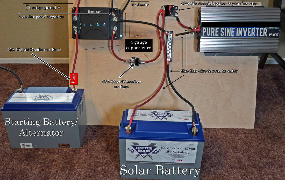
Now, when you say you have two battle born 100 Ah batteries, are you using both to power the inverter at 12 volts?
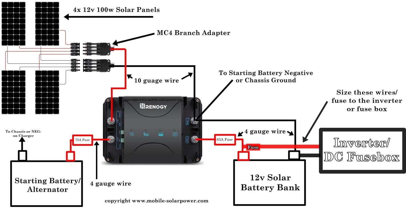
Or are you going to do EXACTLY like the picture and use one for the vehicle starting/charging?
I mistakenly thought you were giving a size range between 2,000 to 4,000 Watts.
OK, if it were mine, and I do screw up from time to time, I would 'Average' the cable size around 3,000 Watts.
That's 000 Ga, (3/0) cables.
12 volt battery/batteries,
That's 250 amp draw at 3,000 Watts (000 Ga.- 3/0), still not maxed out the cable.
That's 167 amp draw at 2,000 Watts (1 Ga), maximum continuous rating for that inverter,
With any energy efficiency at all, you will probably be drawing more in the neighborhood of 1,000/1,500 Watts,
That's 84 and 125 amps respectively, which leaves a HUGE capacity under normal usage.
I would use a 250 or 275 amp breaker on 000 Ga.- 3/0 cable, but I would mount it at the battery if the battery is 'In Doors'
If the battery is in a battery compartment I would armor the cable from battery to interior, and mount the breaker where the armor stops inside.
-----------------
Now, when you say you have two battle born 100 Ah batteries, are you using both to power the inverter at 12 volts?
Or are you going to do EXACTLY like the picture and use one for the vehicle starting/charging?
")