diy solar

diy solar

SunGoldPower SPH5048P reading 25v between neutral and ground, 96v between line and ground!

Gentleman Mike

New Member
Joined
Jan 17, 2024
Messages
31
Location
Saint Louis, MO
Hi all, I'm having an issue with an SPH5048 from SGP. Their support is worthless and they send you on wild goose chases, so I'm wondering if anyone here may have any ideas on whether I've just done something wrong or if this unit is defective.

When on inverter power, on the AC output, I'm reading 25 VAC between neutral and ground and 96 VAC between line and ground. However it does read 120 VAC between line and neutral.

It also read 25 VAC between neutral and ground AS WELL AS line and ground on the AC input side, when I have grid power disconnected.

When grid power IS connected, I still read 25 VAC between neutral and ground and it turns out that this thing is constantly pulling 5-6 amps from the grid even when there's no load!

Something is clearly wrong. Any thoughts? Other than I should have bought a Victron?
 
Grab yourself three regular 120 volt 25-100w bulbs and put them between live and neutral, live and ground and neutral and ground. You know which one should light up and hopefully the other two do not light up, then you can measure the voltages and see if they are just phantom from slight leakage which is perfectly normal.
 
Grab yourself three regular 120 volt 25-100w bulbs and put them between live and neutral, live and ground and neutral and ground. You know which one should light up and hopefully the other two do not light up, then you can measure the voltages and see if they are just phantom from slight leakage which is perfectly normal.

Thanks I'll give that a try and report back. What's up what that constant 6 amp draw though?

And shouldn't I still read 120 VAC between line and ground despite a slight leakage?
 
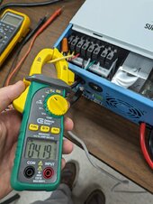
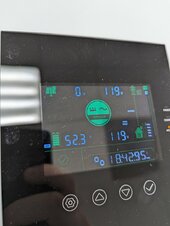
Yeah, here we go it's actually pulling 4.2 amps from grid as a baseline, not 6 amps. Then if I add output loads on top of that, it adds upon the 4.2.

PXL_20240129_235216074.jpg

That's while it's not charging the battery (in fact I flipped off the battery circuit breaker and it remains the same) -- you can see it's only doing AC bypass, no power going to the battery.

2.jpg


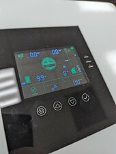
And with no load connected -- 0 watts.

PXL_20240129_235303156.jpg

However, it does NOT do that during system startup/standby mode. Only once it goes into "normal" status and starts feeding AC output. Shouldn't it be maybe 200-300 milliamps with no load and no battery charging?
 
Last edited:
By the way, the 25 VAC between neutral and ground does seem to be some phantom power after all. I couldn't find an unused light socket for that test, but I put a multimeter in amps mode between neutral and ground. Thankfully it didn't blow my meter's fuse and it's only passing a few milliamps between them.

Now it's this constant input draw that's got me concerned.
 
It should only be using ~50W idle. If it's the SRNE I think it is.
Add a known load to test the meter?
 
It should only be using ~50W idle. If it's the SRNE I think it is.
Add a known load to test the meter?

It is a relabeled SRNE, yes.

I've done so with adding a known load, and the meter was known to be good.

I actually wrote some software to read parameters from the unit the other day, and that's where I first noticed that it was reporting 4.2 amp grid input for no good reason. I was wondering if I was reading the data incorrectly, so then I did this with a physical meter... turns out it wasn't a lie, it's really pulling 4.2 amps.
 
Pulling 4 amps is meaningless without knowing the relationship to the AC wave form. It is very common to see current like this with input filters but the power consumption is only a few watts.

This may help with understanding why

Thanks. It makes me curious what other people are seeing for grid input current on their similar SRNE units with no load.

Does the "extra" 4.2 amps still "count" as far as loading the circuit breaker in the panel?

Also, someone just mentioned to me that most of the power coming into this building is actually 3 phase 208 volt and our 120 volt circuits are actually made using one of those legs and that ground and neutral aren't bonded. Could that be an issue?

Another potentially relevant (?) fact is that I'm currently testing this unit using a 5-20P plug into a 20 amp circuit. It's not hardwired into a panel yet, I'm doing some initial testing of it like this before hardwiring. Should be fine, right?

Sorry for the dumb questions, I'm a software guy and slightly below novice level when it comes to electrical stuff. I know just enough to blow myself up.
 
Last edited:
Hmm. I just posted a very similar thread regarding a renogy 48v inverter having 30v between N and G. Sounds like this might be a thing
 
Pulling 4 amps is meaningless without knowing the relationship to the AC wave form. It is very common to see current like this with input filters but the power consumption is only a few watts.

This may help with understanding why

It seems that you're correct. I hooked up a Kill-A-Watt. It is indeed measuring around 4 amps, but the wattage only bounces around 30-50 watts with no load. I guess that 4 amps still counts towards the total going through the input breaker though? Even though it's apparently not 4A @ 120V.
 
Last edited:
Back
Top