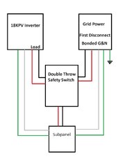
2-pole switch can be used. Both ground and neutral bonding can come from grid connection.
But neutral and ground should travel through same conduit or cable as L1 and L2, with all four wires close together except where they spread just to connects to switches, breakers, etc. Not going around the outside as you show.
One way to accomplish that is a Tee conduit to switch, so L1 and L2 from both grid and inverter go into switch through same conduit, also come back out of switch to load through same conduit. Then neutral doesn't go through switch. Ground does connect to switch.
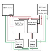
Alternately, Neutral does go through the box which contains switch. L1 and L2 from grid and inverter both enter switch, same or different conduit. Neutral from both connect to an unswitched terminal in the box, while L1 and L2 from each goes to its switch terminal. Ground from each goes to a separate ground terminal in box. All wires L1, L2, N, G leave box (can be a third conduit) to load.
That's just about the switch. If inverter has auto-transformer (especially if it is a 240V only inverter with external autotransformer, that is a different can of worms, not addressed here.
Many inverters have grid input and output, in which case that performs the switching, and you don't need to add one for on/off grid operation.
What you can do is use an interlocked "generator" breaker in the sub-panel to manually bypass the inverter in the event it is disconnected for repair.