diy solar

diy solar

Where to put the inverter?

Electron path has to go up 2 floors (panels cantilevered off deck), back down to basement, across 100 ft of house, up garage walls, over ceiling, and back down the other side. Total run ~250 ft.
This is exactly why a regular grid tie installer would often rather run this as AC than DC, even if the AC voltage is lower.

With AC you get all the options, romex, uf-b, pvc, ent.

With DC you have to use EMT or armored and the inspector will get all squirmy.

If you settle some other facts about the system, like will it have batteries or be grid tied only, will the panels be on a roof anddo you need rapid shutdown compliance, then you will be able to make a decision of AC or DC coupled and only then, finally, will it become clearer whether to make the long run AC or DC.

If you won't be getting inspections or installing rapid shutdown then this all gets very easy, make the long run DC.
 
Last edited:
Are you talking about a 90C rated wire as opposed to a 60C or 75C connection point? Are there derating calcs that need to be made? And why does stranded or solid make a difference?

I'm asking these questions because I used solid 10awg THHN/THWN wire for my 65ft PV run between my ground mount and inverter. Max current from the array is maybe 10A from what I've seen and 10awg is rated to 30A, so I'm not understanding why the type of wire matters.
 
This is exactly why a regular grid tie installer would often rather run this as AC than DC, even if the AC voltage is lower.

With AC you get all the options, romex, uf-b, pvc, ent.

With DC you have to use EMT or armored and the inspector will get all squirmy.

If you settle some other facts about the system, like will it have batteries or be grid tied only, will the panels be on a roof anddo you need rapid shutdown compliance, then you will be able to make a decision of AC or DC coupled and only then, finally, will it become clearer whether to make the long run AC or DC.

If you won't be getting inspections or installing rapid shutdown then this all gets very easy, make the long run DC.

All great points. I must admit that my answer to the original question...
My panels are 250 feet from where the power (110v) is to be delivered.
was based upon the assumption of "250ft" being across a field to a house and, being in the UK, not having to ponder the complexities of inspections or rapid shutdowns. Goes to show how differently things can pan out when one considers the whole detail!
 
This is exactly why a regular grid tie installer would often rather run this as AC than DC, even if the AC voltage is lower.

With AC you get all the options, romex, uf-b, pvc, ent.

With DC you have to use EMT or armored and the inspector will get all squirmy.

If you settle some other facts about the system, like will it have batteries or be grid tied only, will the panels be on a roof anddo you need rapid shutdown compliance, then you will be able to make a decision of AC or DC coupled and only then, finally, will it become clearer whether to make the long run AC or DC.

If you won't be getting inspections or installing rapid shutdown then this all gets very easy, make the long run DC.
Depends on your local regs- here it is quite acceptable to use pvc conduit with the cable inside (TPE 2.5mm^2 for up to 600vdc usually, although 4mm^2 might have to be used on longer runs for voltage drop reasons) for the solar side, which is practically identical to the mains side (TPE 4mm^2 for the mains side)
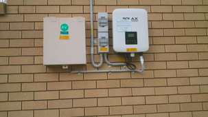
1707737248801.png
From the MCB/cutoff switches to the roof is all done in 2.5mm TPE (twin plus Earth) as a earthed framing system is a requirement here, it makes sense to use TPE... (the two boxes on the left of the inverter contain a double pole isolation switch ie 'quick disconnect' and a double pole MCB rated at the recommended array current fusing (15A in this case)- box on the left does the east facing 3kw array, box on the right does the west facing 3kw array
 
Last edited:
Back
Top