diy solar

diy solar

Eg4 6000xp

@AZSolarJunkie, Thanks for your assessment of the 50amp bypass, I follow and agree.

However, my curiosity is more focused on how a home system could be designed to make use of the full 50amp by-pass. While being limited to the 37.5amp AC IN specification. I feel I'm still mis-understanding something.
As far as I understand, the 37.5 amp input limit is only when it is NOT in bypass…
 
As far as I understand, the 37.5 amp input limit is only when it is NOT in bypass…
Ok got it...thanks!

So then, now I can see why the 6000XP bypass spec its at 50A. It assumes you can charge your batteries while running the rated load.

Bypass current budget (if you'll allow me this term):
  • 25amps (3000w) for running the load while in "bypass mode".
  • 25amps for charging the battery while the inverter is in "bypass mode".
    • Spec: **115A @ 48Vdc
      • AC Input charging watts = (115v x 48v) / 93% efficiency spec. = 5,935.4 watts
      • AC Input charging current = 5,935.4 watts / 240v = 24.7amps or simply 25 amps
👍🏻 Except if your batteries are full or AC charging is disabled, all 50 amps of bypass would be available to pass on to the loads.
 
Have (2) questions related to EG4 6000XP and EG4 LL-S 48V battery.
----
(1) What size cable size from inverter to batter - 1 AWG or 2 AWG?

System will have (2) EG4 LL-S batteries and expand to (4) at some point.

The manual for the EG4 6000XP recommends a 1 AWG cable to connect to battery terminal but the EG4 LL-S manual recommends a 2 AWG cable to connect battery terminal. Seems like many simply recommend going with 2AWG wire.

EG4 6000XP Manual (p.15) - https://eg4electronics.com/backend/wp-content/uploads/2023/10/EG4-6000XP-Manual.pdf
EG4 LL-S Manual (p. 12) - https://eg4electronics.com/backend/wp-content/uploads/2023/09/EG4-LL-S-48V-100AH-Manual.pdf
------
(2) What cable size for connecting battery to battery?

EG4 LL-S come with 6 AWG cable to connect battery to server rack but no mention, that I found, related to battery to battery.


😎Thanks!
 
Last edited:
Have (2) questions related to EG4 6000XP and EG4 LL-S 48V battery.
----
(1) What size cable size from inverter to batter - 1 AWG or 2 AWG?

System will have (2) EG4 LL-S batteries and expand to (4) at some point.

The manual for the EG4 6000XP recommends a 1 AWG cable to connect to battery terminal but the EG4 LL-S manual recommends a 2 AWG cable to connect battery terminal. Seems like many simply recommend going with 2AWG wire.

EG4 6000XP Manual (p.15) - https://eg4electronics.com/backend/wp-content/uploads/2023/10/EG4-6000XP-Manual.pdf
EG4 LL-S Manual (p. 12) - https://eg4electronics.com/backend/wp-content/uploads/2023/09/EG4-LL-S-48V-100AH-Manual.pdf
------
(2) What cable size for connecting battery to battery?

EG4 LL-S come with 6 AWG cable to connect battery to server rack but no mention, that I found, related to battery to battery.


😎Thanks!
Will you be using the battery rack with the integrated bus bars?

Like the battery manual says, the 2 AWG recommendation is for the up to 100 amp continuous output of a single battery. The 6000xp can pull up to 125 amps continuous when putting out its max of 6000 watts, which is why it recommends 1 AWG.

The short 6 AWG cables are meant to connect each battery to the bus bars in the battery cabinet. I know some people use them to connect the batteries directly together, but they’re intended for connecting each battery to shared bus bars. Then you can use 1 AWG to connect the 6000xp to the bus bars.
No battery rack.
 
No battery rack.
In that case just get some bus bars to connect the batteries to and then connect the inverter to the bus bars with 1 AWG. With only 2 batteries it wouldn’t be difficult to connect them both to the bus bars with the short 6 AWG cables, but when you get to 4 batteries you will probably need some longer cables for all the batteries to be able to reach the bus bars. It’s recommended that all the batteries use the same cable lengths to the bus bars.

There are entire threads about people’s recommendations on bus bars. Popular options seem to be the Victron Lynx and the Bluesea bus bars.
 
Have (2) questions related to EG4 6000XP and EG4 LL-S 48V battery.
----
(1) What size cable size from inverter to batter - 1 AWG or 2 AWG?

System will have (2) EG4 LL-S batteries and expand to (4) at some point.

The manual for the EG4 6000XP recommends a 1 AWG cable to connect to battery terminal but the EG4 LL-S manual recommends a 2 AWG cable to connect battery terminal. Seems like many simply recommend going with 2AWG wire.

EG4 6000XP Manual (p.15) - https://eg4electronics.com/backend/wp-content/uploads/2023/10/EG4-6000XP-Manual.pdf
EG4 LL-S Manual (p. 12) - https://eg4electronics.com/backend/wp-content/uploads/2023/09/EG4-LL-S-48V-100AH-Manual.pdf
------
(2) What cable size for connecting battery to battery?

EG4 LL-S come with 6 AWG cable to connect battery to server rack but no mention, that I found, related to battery to battery.


😎Thanks!
Just another view for a worst case perspective:

Looking at the 6000XP output capabilities both peak and continuous. And figuring the needed battery power after factoring the efficiencies of 6000XP;

6000XP Output (W) / Efficiency = Need Battery Power (W)

6000W (continuous) / 0.93 = 6,452 watts of battery (continuous)

11,000W (5 sec) / 0.93 = 11,827 watts of battery (5 sec)

12,000W (3.5 sec) / 0.93 = 12,903 watts (3.5 sec)


Inverter to Battery Server Rack:

This yields a worst case battery current between 6000XP inverter and two EG4-LL-S batteries both peak and continuous;

Battery(W) / Lowest Battery Voltage = Battery (Amps) worst case

Continuous: 6,452W / 48V = 134.4 Amps => 4 AWG NEC 2020 Table 310.17 (Free Air)

Peak 5 sec: 11,827W / 48V = 246.5 Amps => 1/0 AWG NEC 2020 Table 310.17 (Free Air)

Peak 3.5 sec: 12,903W / 48V = 268.8 Amps => 2/0 AWG NEC 2020 Table 310.17 (Free Air)

Note: Note while using two EG4-LL-S batteries you may not have the ability to meet the peaks demands of the 6000XP. This may not be a problem depending upon the demands of your load.

Comments: I would recommend the 2/0 AWG wire between the battery server rack and 6000XP inverter. Yes, it’s a little more expensive but it’s a short run. This would allow for an acceptable level of heating (per NEC 2020) within the wiring during peak operation of the 6000XP inverter.


Battery to Server Rack Cable size:

Assuming the two EG4-LL-S batteries are in a server rack utilizing the buss bars. The 6 AWG wire that comes with the battery is almost adequate per NEC 2020 Table 310.17 (Free Air) but you may want to consider another battery so that three batteries share the peak demand.

6 AWG -> 105 amps => assuming 90 degree C, THHN or USE-2, Free Air, per NEC 2020 Table 310.17

4 AWG -> 140 amps => assuming 90 degree C, THHN or USE-2, Free Air, per NEC 2020 Table 310.17

Two sets of 6 AWG wires connecting two batteries to buss bars within server rack allows for 210 amps of wire capacity to the inverter. This is ok for continuous however during peak time you may generate a little heat on your cables.

When you add a third battery your wire capacity allows for 315 amps to the inverter. This arrangement would meet the demand of the 6000XP inverter. However, if two batteries are all you have at the moment, then 4 AWG wires will give you a 280 amp capacity to meet the peak demands of the inverter.

Hope this helps
Those short peaks of surge power though don't require heavier gauge wire necessarily. The NEC recommendations for wire gauge amps is for continuous power. Short surges of higher amps should be fine. Still, heavier wire is always better ;) I do 2/0 from the rack bus bars to a lynx power in, and 1/0 from the lynx to each inverter. Using the short 6 awg wires from each battery to the rack bus bar I've never seen them get warm at all even during surge demand...
 
Have (2) questions related to EG4 6000XP and EG4 LL-S 48V battery.
----
(1) What size cable size from inverter to batter - 1 AWG or 2 AWG?

System will have (2) EG4 LL-S batteries and expand to (4) at some point.

The manual for the EG4 6000XP recommends a 1 AWG cable to connect to battery terminal but the EG4 LL-S manual recommends a 2 AWG cable to connect battery terminal. Seems like many simply recommend going with 2AWG wire.

EG4 6000XP Manual (p.15) - https://eg4electronics.com/backend/wp-content/uploads/2023/10/EG4-6000XP-Manual.pdf
EG4 LL-S Manual (p. 12) - https://eg4electronics.com/backend/wp-content/uploads/2023/09/EG4-LL-S-48V-100AH-Manual.pdf
------
(2) What cable size for connecting battery to battery?

EG4 LL-S come with 6 AWG cable to connect battery to server rack but no mention, that I found, related to battery to battery.


😎Thanks!
@HighCountry

Created four drawings showing your potential configurations based upon using buss bars or no buss bars as well as 2 batteries versus 3 or more batteries.

When using two EG4-LL-S batteries with the 6000XP, the capacity of the two EG4-LL-S batteries becomes fully utilized under peak conditions. So… when you get a handle on your specific loading of 6000XP, you can determine if there is any urgency of obtaining a 3rd battery.

These wires sizes are based off the NEC 2020 Table 310.17 (Per EG4-LL-S page 13 manual).

So back to the two-battery configuration. After looking at the battery specifications, it appears the two EG4-LL-S batteries may be able to support the 6000XP under peak surge conditions of 12,000W @268.8 amps for 3.5sec. In practice, I have not verified this surge condition. I suspect it based upon the BMS reaction to the surge versus the battery cells.

This is why if there is a chance the two-battery configuration can deliver the surge demand. Then the recommended 4 AWG wire would additionally be less resistive in the effort to support the surge over the 6AWG wire delivered with the battery.

If however, the two EG4-LL-S batteries cannot deliver the 6000XP 268.8 amps surge then your system would need 3 batteries to support the 6000XP surge requirements and now the 6AWG wire becomes the recommend wire size in a buss bar configuration (per NEC2020 Table 310.17).

The calculations in these drawings can be found in my previous post#48.

Hope this helps.

Drawings:
1710704988745.png
 
@HighCountry

Created four drawings showing your potential configurations based upon using buss bars or no buss bars as well as 2 batteries versus 3 or more batteries.

When using two EG4-LL-S batteries with the 6000XP, the capacity of the two EG4-LL-S batteries becomes fully utilized under peak conditions. So… when you get a handle on your specific loading of 6000XP, you can determine if there is any urgency of obtaining a 3rd battery.

These wires sizes are based off the NEC 2020 Table 310.17 (Per EG4-LL-S page 13 manual).

So back to the two-battery configuration. After looking at the battery specifications, it appears the two EG4-LL-S batteries may be able to support the 6000XP under peak surge conditions of 12,000W @268.8 amps for 3.5sec. In practice, I have not verified this surge condition. I suspect it based upon the BMS reaction to the surge versus the battery cells.

This is why if there is a chance the two-battery configuration can deliver the surge demand. Then the recommended 4 AWG wire would additionally be less resistive in the effort to support the surge over the 6AWG wire delivered with the battery.

If however, the two EG4-LL-S batteries cannot deliver the 6000XP 268.8 amps surge then your system would need 3 batteries to support the 6000XP surge requirements and now the 6AWG wire becomes the recommend wire size in a buss bar configuration (per NEC2020 Table 310.17).

The calculations in these drawings can be found in my previous post#48.

Hope this helps.

Drawings:
View attachment 202681
Thanks!

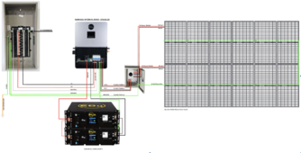
EG4 LL-S manual reads at page 14: "Attach a grounding wire from the rack/cabinet to an equipment grounding conductor, then terminate the EGC at a grounding electrode."

Does the wiring diagram below comport to that standard by grounding batteries (or rack) directly to PE ground on EG4 6000XP?

Off Grid Solar System.png
 
Last edited:
Thanks!

EG4 LL-S manual reads at page 14: "Attach a grounding wire from the rack/cabinet to an equipment grounding conductor, then terminate the EGC at a grounding electrode."

Does the wiring diagram below comport to that standard by grounding batteries (or rack) directly to PE ground on EG4 6000XP?

View attachment 202729
Nice Drawing.

Yes, keep with your #8 AWG THWN-2 wire size for your grounding conductor.

Connecting the EG4-LL-S battery grounds to the internal 6000XP ground buss bar and continuing the connection back to the ground buss bar within your main service panel is correct.

Additionally, you have only one N-G bond connection which is in your main service panel. (6000XP N-G software disabled)

I'm assuming meter is connected directly to your main service panel.

Will you be permitting this system? Just asking.
This is completely off grid - no power lines for 5 miles!! County said I don't need to get approval since out in the sticks (no inspector will drive out) but to make sure it's to code in case the day comes that they want to check things out.
 
This is completely off grid - no power lines for 5 miles!! County said I don't need to get approval since out in the sticks (no inspector will drive out) but to make sure it's to code in case the day comes that they want to check things out.
Okay.

My only point in asking was to make you aware of how you would bring the "Direct Current (PV) into your building". The new code rules (NEC 2020 690.31 (D)) require the use of "metal' conduit at the entrance point into your building up to your equipment (inverter or DC disconnect). Your are allowed the last 6ft to be exposed for connection purposes. When outside your allow to use PVC conduit.

I say this to you because I was unaware and planned PVC conduit all the way. Anyway, I'm still trying to decide between 3/4" EMT or the 1" flexible metal conduit (FMC). Again, just a heads up, I know you are off grid, but you still want to be safe and aware of were the code is focusing.
I see... Once the DC PV goes into the cabin, it needs to only go roughly 4-6ft. I was considering putting a DC disconnector (interior or exterior?) at the cabin thus I think the transition from PVC conduit to metal should be super easy.

While we are on this topic... Is there a depth that PVC conduit must be buried? Our plan: schedule 40 at 18in as it never crosses any road just dirt driveway.
 
Last edited:
I see... Once the DC PV goes into the cabin, it needs to only go roughly 4-6ft. I was considering putting a DC disconnector at the exterior of cabin thus I think the transition from PVC conduit to metal should be super easy.

While we are on this topic... Is there a depth that PVC conduit must be buried? 18 in is what I assume as it never crosses any road just dirt drive way at one point.

18" for PVC conduit using individual THWN-2 conductors

Schedule 40 PVC is commonly used for the installation of underground wiring to a detached garage or tool shed, or it can be used indoors like a garage or tool shed. The NEC requires heavy-duty Schedule 80 PVC on the side of a building where you transition from below ground to above ground as added protection from lawnmowers and weed whips.

The wall cross-section for Schedule 80 PVC is thicker, but the external diameter of Schedule 40 and Schedule 80 is identical, so all the PVC connectors and couplings are interchangeable.

Reference: NEC Table 300.5 Minimum Cover Requirements
 
Last edited:
@Bridgetown Thanks for the details... Very helpful for my build.

I was wondering if a lightening and surge arrestor is needed for the EG4 6000XP?

On Signature Solar, their kit with the EG 6000XP has (2) AC arrestors and (2) DC arrestors. DC arrestors - one at the PV combiner box and other at the main breaker. AC arrestors - both at the main breaker (L1 and L2).

Complete Off-Grid Solar Kit - https://signaturesolar.com/complete...split-phase-6400-watts-of-solar-pv-kit-e0008/
I understand these lightning arresters from Midnight solar are quality surge arrestors. If your area is susceptible to lightning then its recommended. Especially if you know of equipment form your neighbors or yourself of being damaged by lightning.

Installation becomes important (beyond hooking it up), meaning the main objective is to divert unwanted energy from your equipment. So your ground path needs to be kept short as possible back to your ground rod. Avoid parallel runs with other wires, again its about getting the energy directed to ground (Earth) and away from your equipment.

In other words, after the surge arrestor does its job, don't mess it up by running the ground wire in parallel with others wires that could inadvertently re-induce the energy back into your equipment. The objective is to get that energy to ground (Earth).

Just be aware, grounding for lightning and system grounding for electrical safety are two different objectives.

So your installations effectiveness is proportional to your ground path distance. So if you install an surge arrestor with a long return path with the ground running parallel to other wires, the surge arrestor starts losing its effectiveness and starts to become more of a mental placebo (piece of mind). Just me 2 cents
 
Thanks!

EG4 LL-S manual reads at page 14: "Attach a grounding wire from the rack/cabinet to an equipment grounding conductor, then terminate the EGC at a grounding electrode."

Does the wiring diagram below comport to that standard by grounding batteries (or rack) directly to PE ground on EG4 6000XP?

View attachment 202729
how did you create this graphic? I would like to be able to do the same.
 
Back
Top