You should probably start a separate thread for autotransformer use. This thread is long, and about safety issue.
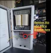
My transformer is 5kw, would it be a good idea to follow this suggestion on the attached picture to prevent transformer failure in the event the transformer gets overloaded? if so what size breaker should replace those terminals?
"5kw", you say. Does the documentation say what maximum imbalance between L1 and L2 is allowed?
You already have a breaker ahead of the transformer. Which is better than what the picture recommends.
Either should work. If there is a breaker panel feeding it, breaker could go there. If someone fed directly from inverter, then DIN rail breaker inside autotransformer box works.
But , I would change it to a 25a , instead of the 30a.
To match the transformer output rating.
This is where I disagree. Tim is a professional in the field of electrical work, but I disagree that the inverter would be protected with that large a breaker.
25A x 240V = 6000W
6000W x 80% = 4800W continuous.
If transformer could handle 5kW, I would agree. The data sheet may say 5kW, but it isn't true. Focus on what "imbalance" it says is allowed, which means neutral current.
But if you put 4800W 120V load on one leg, 4800W / 120V = 40A.
The data sheet I saw said max 3000W imbalance. 3000W / 120V = 25A max neutral current. Not 50A, not 40A.
25A x 120V = 3000W. 3000W / 120V = 12.5A. There is only 12.5A flowing through L1 winding of transformer, and only 12.5A flowing through L2 of transformer. That's why I said earlier that OCP needed to be 12.5A. Maybe 15A 2-pole breaker, which not only disconnects transformer but also disconnects all loads to protect from lost neutral.
To protect the transformer, I say it needs to either protect neutral to 25A max (could go 30A or so to allow 25A continuous), or have temperature sensor. When the protection trips, it has to turn off L1/L2 power into the transformer and disconnect L1/L2 from the load panel as well. This is what Victron did - either 32A or 100A 2-pole breaker, and a temperature sensor wired to a remote trip "breaker" ganged to that 2-pole breaker.
The deal is, 240V loads and a combination of 120V loads on L1/L2 could be powered directly from inverters without any current through the transformer. Imbalanced loads produce current through the transformer.
As long as you make an attempt to balance your 120v loads, you should be fine.
As long as you put no more than 25A on either L1 or L2 after the transformer you should be fine.
However, if you protect with 12.5A or 15A breaker like I suggest, you could only have one of the two 25A loads on at any time. If both 25A loads are on (one on L1, one on L2), that would trip the breaker.
A protection scheme like Victron designed is needed.