diy solar

diy solar

Four 12V 150watt mono crystalline panels. Parallel vs. Series-parallel vs. Series?

Don't. EPEver's are notorious for getting stuck at lower voltage at sunup and getting stuck there. Get any brand other than EPEver (I prefer HQST or Rich Solar for value) and get more amperage (that Vevor should be fine) and leave the panels alone other than cleaning them.
obscura1714272921824.jpg
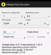
Well according to my math, it would work with a 1% voltage drop between both strings by making the series connection down at the bus bar. Is it worth it? Not sure... I already have the mc4 extension cables on the way... So I'll probably just wait to do it that way.

I'm definitely looking to upgrade the SCC so I can utilize all the wasted power, but like I said I've never had issues with this controller getting stuck at lower voltages... Until my panels got really dirty.

I'll aim for that 50amp then. Thank you again
 
I'll just wait for the mc4 extenders. Even though the distance should be able to handle 600 watts at 87volts if I connected down at the busbars, I'm not sure how the panels would handle that.

Either way, with a 5ft 12guage mc4 extender I'm only getting .2V voltage drop vs. My weird idea I would get .4V voltage drop.
 
Yeah, your wire is fine, it's the EPEver that's causing the problems. Once you get the new MPPT I highly suspect your problems will go away.
 
Yeah, your wire is fine, it's the EPEver that's causing the problems. Once you get the new MPPT I highly suspect your problems will go away.
You know... That glitch you mention about epever I wonder if it has to do with the order of operations (connecting the controller to battery first then PV) because after disconnecting and reconnecting the solar yesterday, and then installing that 600watt breaker, I'm getting much higher output.

I'm curious how long until I encounter this glitch again if I keep the SCC powered on 24/7. I use a LVD relay for my inverter so this could be a good test.
Nope, it's a known issue with the MPPT programming in the SCC.
 
That's one of life's great mysteries... :unsure:
I came across this thread with firmware update files


I already have it setup to connect on my PC to the controller with the rs485 usb adapter. I think I'll try updating the firmware before tossing it in the trash.
 
I came across this thread with firmware update files


I already have it setup to connect on my PC to the controller with the rs485 usb adapter. I think I'll try updating the firmware before tossing it in the trash.
Yup, just encountered that bug again. Glad I installed that circuit breaker on the PV side lol. I was stuck at 19V 2.3amps. Flipped the manual switch on the breaker and it shot back up to 87V 2.3amps. Which is great news for the panels.

Really looking forward to updating the firmware now
 
What a day.

My circuit breaker could have been what was causing the drop in current on the PV side... It finally popped up in smoke when I pressed the manual breaker button. Solar panels are fine, wiring in tact.

I tried updating the firmware while I had the PV disconnected only to find out I have the oldest (like very first version) of the epever that never got a firmware update. Newer tracers had the ability in the PC software to tune the low temp charge disconnect with the temperature probe but I never could. I've only ever used the MT50 to fine-tune the values in user mode (which was tricky but I found a way to force the controller in Max output mode and hold at a comfortable voltage of 13.8 while skipping the equalize stage)

Anyways... I disconnected that garbage circuit breaker. Keeping the solar panels in series, skipping the firmware update and crossing my fingers it works well enough until I get that vevor 50amp.

Just to be on the safe side I'm also setting up a high voltage disconnect on the charge controller charge circuit/battery connection so it'll protect everything else from the controller.

I might go for an inline fuse instead since arcing is a problem with circuit breakers as well as heat when they pass current.
 
Small update...
Found a physically hot ground wire in the solar panel junction box next to my solar charge controller. Spent the day wire brushing everything with white vinegar, spraying it down with electronic cleaner and dielectric grease to finish the job.

This old, version 1 un-updateable Epever seems to like the whole solar rack in series; it stayed at 87V all day and didn't once dip below the max output of 30amps at 12V until the sun went behind the horizon. Still generating 24 watts in the shade with dirt on the panels 😆

I probably need a circuit breaker rated for that high voltage (homer Simpson doh moment) ironically they're cheaper too.

Now I'm reading on this forum that even though epever states 3x overpanelling is supported for short circuit currents, it's still recommended to pre-charge the PV input even after the SCC is connected to the 12V battery source.

Is this true? Hmm...
 
New goal:

Install precharge 3-mode battery switch on PV side

Setup high voltage disconnect on existing charge circuit relay

Upgrade charge controller to 50amps

Enjoy no electrical fires
 
Once I get the new SCC I might see if I can get this open source EPever firmware to work.

Apparently they tightened the MPPT tracking delays, but at the cost of losing control of the load port.

Requires special hardware to force flash to

Apparently all epever controllers run on this firmware

 
For anyone else who stumbles upon this thread,

Hours of troubleshooting (after experiencing the lockup bug again post-ground fix on the PV array)

*Facepalm* I had epever send me the charge logic schematics and tuned my settings accordingly. I had float charge set to the same voltage as boost charge. What was odd is the controller accepted these values without error.

Setting boost charge to 13.8V at 180mins max duration, equalize duration to 0 with a voltage above boost, boost reconnect voltage to 13.6V, and float voltage to 13.7V, it's finally working right.

The boost charge is a curve down from max current until 180mins is reached, then it will fall to float at 13.7V with a small current (possible lockup state experienced) setting boost reconnect to 13.6V reengages the peak boost current tapering slowly until 180mins is reached again. Any load on the system at 13.7V reengages boost by dropping to 13.6V, will it will sit at 13.8V 30amps (~439 watts) for another 180mins.

This way I get to top off the battery, and instead of starting another drain/recharge cycle it's constantly reengaging boost in the peak curve powering the loads almost entirely on solar.

A bit like how modern phone battery BMS's work through USB-C bypass, also called "idle" charging.
 
Last edited:
Back
Top