diy solar

diy solar

Uneven discharge from multiple battery packs.

hpeyerl

New Member
Joined
Mar 22, 2022
Messages
94
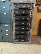
I have a rack of 8 identical Shoto Lifepo4 48x100 telecom batteries. The batteries were new in-crate when I received them and have contiguous serial numbers. They're connected to one another via RJ45 and talk to one another via CAN. My Sol-Ark doesn't know how to talk to them but Solar-Assistant has been adding protocol changes to their Narada protocol to communicate with my batteries.

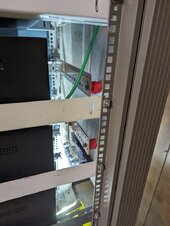
The batteries are all connected to two solid copper bus bars, 2 inches wide, .125" thick, with machined holes. All the cables are identical length/awg and the fasteners were all torqued down the same. In the center of the positive bus bar I have a T-class fuse and 4/0 going to my Sol-Ark. I've included some pictures that may or may not tell you much.

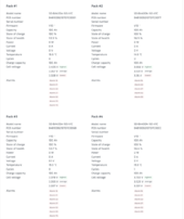
I recently setup TOU on the Sol-Ark and in Solar-Assistant am seeing widely disparate discharge levels on some of the batteries. The lights on the front of the units seems to accurately portray what Solar-Assistant is telling me.

I'm thinking this is some sort of actual problem in the batteries and not how I've got it hooked up/configured. Anyone have any thoughts on how I should deal with this? My first thought is I'm going to make all new cables from scratch.
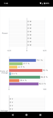
Screenshot_20240506-114836.png
PXL_20240312_164813533.jpgPXL_20240114_202732155.jpg
 
Last edited:
State of charge is interesting. What is the actual voltage of each battery? Use a separate voltmeter.
Have the batteries been through a charge/discharge cycle?
 
State of charge is interesting. What is the actual voltage of each battery? Use a separate voltmeter.
Have the batteries been through a charge/discharge cycle
Carlos disabled TOU and now the batteries are back up to 100% SOC but I can go out later this morning and measure them.

I haven't intentionally put them through a full discharge but they've been on my system for a few days with TOU enabled so they discharged (unevenly) and recharged a few times. I suspect that's not what you mean though?

(this is a new system for me and I'm still just learning).
 
SOC as reported by the BMS in each battery.
Charge the whole thing as configured to at least 55.6 volts to reset and coordinate the BMSs.
Hmm... just noticed SA is not reporting pack voltage.
You need to put a multimeter on the packs to determine a baseline.
 
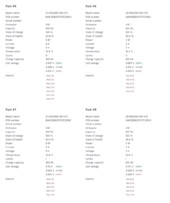
Here's what SA has for each battery.. With each revision Pierre has released, more of the information has been filled in. I think the Alarm's are bogus because they're not even listed in the Modbus manual or I'm not understanding how to parse the Alarm bits.

State of health is curious, to me. I'm wondering if that's the Pack voltage and SA is attributing the wrong register to Health.

Screen Shot 2024-05-09 at 7.19.57 AM.pngScreen Shot 2024-05-09 at 7.20.08 AM.png
 
PACKS 2, 4, 6, 7 & 8 ARE ALL TRIPPING HVD Disconnect as they are Well Over Allowable Voltage Ranges. HARM IS BEING DONE !
Your Charge Profile is obviously WRONG and needs immediate attention !
See suggested "48V" charge profile below.

! Stop, do not replace the cables without doing the following:
- recheck that they are "Clean & Tight" and that no corrosion or anything is playing a part.
-- While doing the above, also use a DMM and do a continuity check and if possible a resistance test which would any indicate issues.
- Bus Bar Connections are a common cause actually.
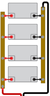
1715259751015.png

As shown here (from the victron wiring guide) when connecting packs into a bank, it is best to feed Pos & Neg from the opposite ends on the common dc bus. This does actually solve some usual issues.


- Charge profiles can also be a major source of problems. LFP like all chemistries has 2 Voltage Ranges. The allowable range which is the voltages where there is no harm or damage to cells/battery packs. This range is from 2.500 to 3.650 Volts per cell but this is NOT the working range that is to be used daily and which is actually responsible for delivering the actual AH rating of the battery packs. The Working Voltage range is from 3.000-3.400 Volts per cell with Nominal Voltage being 3.200 (aka 50% SOC)
A "48V" packs consists of 16 Cells in Series. That places the Working Range voltage @ 48.0 to 54.4 Volts because the Voltage Curve for LFP is Very Flat !

When charging with a profile that is a bit too aggressive and pushing beyond working voltage range, cells can become "runners" and quickly race to High Voltage Cutoff (usually 3.650V) at which point the BMS will cutoff to protect the pack. This is proper & correct behaviour. As the cell(s) settle the BMS will reconnect until the runner causes cutoff again (happens quickly). This will prevent the remaining cells to reach full as the continual on/off charging hampers the entire pack. When multiple packs are within a bank, this will cause a cascading effect because the amperage incoming will vary up & down as a pack or two start to cutoff. Ultimately as this proceeds along, each pack will begin to take "the hit" as it were and the bank becomes handicapped. THIS IS OBSERVABLE "IF" can can monitor each battery pack while charging above the 75-80% point. Runner cells will become apparent and start indicating at what voltage level they will start to run. Another side-effect that contributes, is that if 1 packs can't keep up but the others do so, once charging essentially stops, they will attempt to Back Charge the one weaker pack, wasting their stored energy.

A Good "Moderate & Reasonable" profile that works in most cases without issues that will provide the full capacity available from the packs without stressing any of them and maximizing the lifecycles.

Bulk / Absorb: 55.2V (Absorb for 45 minutes (3.45vpc) (some call this boost)
Equalize: OFF
Float 55.0V (3.437vpc)
MIn Volts: 42.4V (2.650vpc)
Max Volts: 57.2V (3.575vpc)
Rebulk Voltage: 51.2 (3.200vpc)
End Amps/TailCurrent: *1 (Triggers change from Absorb to Float)
(*1): End Amps is calculated: (100AH X 0.05 = 5A or 280AH X 0.05 = 14A.
EndAmps = TailCurrent
Coulumbic Efficiency / Battery Status Meter Efficiency for LFP = 99%.
This gets the bank charged to full with high amps (Constant Current Constant Voltage) and then float (Constant Voltage, Variable Current) tops off so the cells are at 3.437Vpc. I
! Do Not forget to adjust for Voltage Offsets between Actual Voltage @ Battery Terminal & at Solar Controller.

quick-voltage-chart-lfp-jpg.150247
 
Ok. That's a lot of information so I'll have to absorb it. The datasheet for these batteries says Boost/Float is 56.4/54.

I'll go out and unbolt all of the battery terminals so they can all sit by themselves while we sort this out.

I was told that these batteries were built with an extra cell for Telecom requirements.

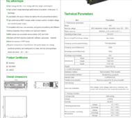
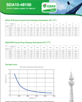
For some reason it won't let me attach a file so here's a screenshot from the datasheet.

Screen Shot 2024-05-09 at 7.43.19 AM.pngScreen Shot 2024-05-09 at 7.44.33 AM.png
 
Per the Spec Sheet they are 16S or 51.2V Nominal.
Many telecom rack batteries like PylonTech are 15S or 48.0V Nominal. These are commonly used with equipment that was designed for 48V Lead Acid batteries that cannot be programmed to take full advantage of LFP. LFP is the closest Lithium Chemistry to the old Lead Acid batteries.

Far too many commercial battery producers (off shore especially) want to push packs to the edges to make them look better but are causing harm. We have seen this far too many times and the results are NEVER good.

Note that at their recommended discharge cutoff @ 40.0V means the cells would be at or below 2.500 causing harm ! Additionally, and half decent BMS would be "bricked" because it is too low to recover & accept a charge, short of having an emergency override function. (You will not get that unless you buy really expensive ESS Battery Packs.

Also their TEMP SETTING ARE BAD ! You CANNOT EVER Charge LFP below 0C/32F !!! ABSOLUTELY NOT ! Additionally you can only charge at 0.2C (20A) till the cells reach +5C/41F. OKAY - Several RED FLAGS here... Use Industry Standard info (as I provided) and your good to go, their marketting/sales shlock is NOT trustworthy.

PS: :read Acid batteries are "Brute Force" tech and they can be mishandled somewhat. LFP like ANY Other Lithium Based Chemistry is NOT Brute Force Tech ! It IS MilliVolt & MilliOhm sensitive and must be dealt with accordingly.
 
! Stop, do not replace the cables without doing the following:
- recheck that they are "Clean & Tight" and that no corrosion or anything is playing a part.
-- While doing the above, also use a DMM and do a continuity check and if possible a resistance test which would any indicate issues.
- Bus Bar Connections are a common cause actually.
[I've just come back inside]

All of the batteries are disconnected at the positive.

The batteries are turned on and they are connected to one another via CAN/RS485.

There is no continuity (infinite resistance) across the +/- terminals of each battery.

Each of the positive cables measures .4ohm to the bus bar.

Half of the negative cables measures .4ohm to the bus bar. The other half flip between .3ohm/.4ohm.

(Fluke 79-III. I have an HP3478a if we need more accurate measurements).

Battery voltages are:

Serial#Voltage
44153.8
43953.8
44454.0
44053.4
44353.9
43753.5
44253.8
43853.9

Sadly, there's not an easy way to correlate the above serial number to the SA Pack# because the batteries negotiate their Modbus addresses when they power up so they're dynamic. I had asked Pierre if he could put the Serial# into SA but he hasn't (yet?) because that way I could correlate the barcode on the front of the battery to what's in the dashboard. Thus, I have no way to really know which battery in my initial screenshot corresponds to which physical battery I'm measuring now.

One thing I guess we can confirm is that the 'Health' reading is not the same as the actual Voltage.

When I first activated the batteries, I set the float voltage to '54' in PowerView but I note that it has reverted to 55.7 for some reason. I also had 'Battery Capacity' set to 800, and it's changed to '801' which is probably insignificant but leads me to wonder why the settings are changed. I know @Carlos_Sol-Ark was helping me with the TOU settings but it seems unlikely he modified the battery settings(?).
 
So if I were to understand the data posted by @Steve_S, I would translate that to Sol-Ark settings like so?


Max A Charge(0~275A): 100
Max A Discharge(0~275A): 185
Batt Empty V(41-63V): 42.4
Batt Resistance(0~200mΩ): 8 (?)
Batt charging efficiency(0~100%): 99
Batt Shutdown %(0-100%): 20
Batt Low %(0-100%): 35
Batt Restart(0-100%): 50
Float V(38-61V): 55
Grid Start %(10-90%): 55
Grid Start A(0~275A): 80
Equalization Days(0-90): 0
Equalization Hours(0-10): 0
Absorption V(38-61V): 55.2
Equalization V(38-61V): 56
TEMPCO(mV/℃/Cell)" -0
 
I'm not familiar with Sola-Ark product settings. If I interpret the naming conventions correctly, it all appears correct. Although, I'm not sure how the % for Batt Low is calculated in this instance.

Using your DMM, check the battery voltage at the battery pack terminals, the main dc busbars and then at your solar-ark's Batt terminals. Remember to correct for voltage differences, typically when charging, the offset will be less than when discharging, there is always a voltage difference due to loss, from wire length, every terminal, connector & fuse/breaker etc along the path.

For example, I assume that the "Batt Empty V(41-63V): 42.4" setting also shuts down the Inverter when that voltage is reached. Now that is 2.650 volts per cell and just right, to prevent bricking the Pack. (that depends on the BMS but best be safe) But, is what the Inverter reads if not correct could have unpleasant consequences. Generally, the voltage difference is not very much, maybe +/- 0.5V or so, but if it is higher it may indicate undersized wiring or a possible connection problem.
 
So if I were to understand the data posted by @Steve_S, I would translate that to Sol-Ark settings like so?


Max A Charge(0~275A): 100
Max A Discharge(0~275A): 185
Batt Empty V(41-63V): 42.4
Batt Resistance(0~200mΩ): 8 (?)
Batt charging efficiency(0~100%): 99
Batt Shutdown %(0-100%): 20
Batt Low %(0-100%): 35
Batt Restart(0-100%): 50
Float V(38-61V): 55
Grid Start %(10-90%): 55
Grid Start A(0~275A): 80
Equalization Days(0-90): 0
Equalization Hours(0-10): 0
Absorption V(38-61V): 55.2
Equalization V(38-61V): 56
TEMPCO(mV/℃/Cell)" -0
I suggest running in voltage mode until you are sure soc is correct.
 
I'm not familiar with Sola-Ark product settings. If I interpret the naming conventions correctly, it all appears correct. Although, I'm not sure how the % for Batt Low is calculated in this instance.

Yes, so maybe I should do as @DIYrich suggests and run it in SOC-V instead of SOC-%.

Using your DMM, check the battery voltage at the battery pack terminals, the main dc busbars and then at your solar-ark's Batt terminals. Remember to correct for voltage differences, typically when charging, the offset will be less than when discharging, there is always a voltage difference due to loss, from wire length, every terminal, connector & fuse/breaker etc along the path.

Right. Good point.

For example, I assume that the "Batt Empty V(41-63V): 42.4" setting also shuts down the Inverter when that voltage is reached. Now that is 2.650 volts per cell and just right, to prevent bricking the Pack. (that depends on the BMS but best be safe) But, is what the Inverter reads if not correct could have unpleasant consequences. Generally, the voltage difference is not very much, maybe +/- 0.5V or so, but if it is higher it may indicate undersized wiring or a possible connection problem.
Another concern I have is the pack voltage is only really accurate if the batteries discharge evenly.
 
Another concern I have is the pack voltage is only really accurate if the batteries discharge eveevenly.
I would set at 44 to 48v to stay well above 2.50v per cell. Not much power in that range. You also reserve a little for "emergency", and for inverter standby (periodically power rsd for panels until they start producing).
 
Another concern I have is the pack voltage is only really accurate if the batteries discharge evenly.
Once the entire bank get's "settled" and working properly after a few cycles with a proper profile, they should all level up & balance out. That being said, it will NEVER be "perfect" there will always be a wee bit of deviation between packs which is normal & expected. Now that deviation should not be significant as such, typically < 0.5 Volts when under a load.

As stated before, All Lithium based chemistries are MilliVolt & MilliOhm sensitive but Temperatures are also a BIG factor. Pack temperatures do affect the performance of the cells within.

Case example: I heat my Powerhouse in winter and keep it at 15C/59F. I had a rack-shelf through couple of winters with my packs stacked up. Closest to the floor would be at 10C, each pack up increased by 1 to 1.5C temp. The bottom (coolest) pack took charge slower & discharged slower then the ones above it. Not significant but easily observable. The entire Bank was subsequently affected but not really significantly (I do have more reserve storage than most due to my location & conditions that do happen). Even 1C temp difference affects the packs. Then I changed the layout and placed all packs on one shelf @ 36" above floor level and all packs stayed at same temp and were much happier overall.
 
I'll be monitoring the individual pack temps to see if I need active airflow around them.

This is why I've put my batteries in my heated/heatable shop while the inverter and everything else is in an attached 'shed'. I can control the temps especially since it does get down to -40C here on occasion (Alberta).

I might consider doing a Modbus proxy so I can have my own script monitor the batteries in between SA queries. The batteries have registers that allow me to enable/disable either the charge circuit and discharge circuit so my script could theoretically even intervene if a pack goes out of range.

Another register named "Mode control" is interesting:

Code:
0x0101-Power management constant voltage discharge ;
0x0202 - reserved
0x0303 - battery characteristic discharge mode ;
0x0505 - maintenance;
0x0606 - production test
0x0707 -Self-managed constant voltage discharge (self-following)

Last time I dumped all the registers, Mode was set to 0x0707 so that begs the question "does self-managed" mean the batteries manage it themselves, or does that mean discharge is managed by the consume (inverter)...
 
Back
Top