diy solar

diy solar

120-240 Dilemma- Growatt SPF 6000T DVM-MPV... Did I buy the wrong ALL in ONE?

Habilis

New Member
Joined
Apr 27, 2022
Messages
24
Hello there people more knowledgable than myself!!
Im the proud new owner of a Growatt SPF 6000T DVM-MPV. My decision to buy was based on powering our cabins 120V circuits 1st but having the robust ability to run our 240 V well pump as a bonus. The documentation from Growatt is confusing me... in the "AC Wiring" section of the manual it looks like I can do ONE OR THE OTHER but NOT BOTH. Also when I look at their diagram I find it odd there's not much mention of bonding or grounds... its occurring to me while I type... Did i buy a grey market gizmo that doesn't conform to NEC? Its been 35 years since I wired a house, so my skills are in the tank. Im asking here because Im having a little trouble getting Growatt to respond to my queries ?.
Thanks in advance for assisting old novice, any pointers on this issue truly apreceated!
Cheers
 

Attachments

  • 0571AC26-3EAC-4E81-9F19-C5DB989A86B6_1_201_a.jpeg
    0571AC26-3EAC-4E81-9F19-C5DB989A86B6_1_201_a.jpeg
    457 KB · Views: 39
Arguably, any unit that isn't UL1741 listed (I don't see that one is) isn't NEC compliant.

The wiring is definitely confusing. You can confirm for yourself if it's truly split phase with a VAC voltmeter:
L1-N: 120VAC
L2-N: 120VAC
L1-L2: 240VAC

you can also check for ground/bonding after turning the inverter off and checking continuity between N and G.

Good luck getting anything at all out of Growatt. Way better option to buy from a seller in the U.S. for support.
 
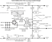
Growatt SPF 6000T is a low freq inverter with a center tapped large heavy weight output transformer.

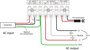
They only provide L1 & L2 input for 240vac. The output has L1, L2 and neutral for 240/120v. When running with AC input, either grid or generator only connect up input to 240vac AC and leave generator/grid neutral not connected. Make sure you connect grid box or generator ground wire up to inverter ground input. Any grid neutral-ground bonding in main breaker box might cause a problem, explained below.

If you common connect an AC input 240/120vac neutral to output neutral you may have output transformer attempting to correct any imbalance in input 120vac L1-N or L2-N voltage. It likely will not be a big issue if AC input is fairly well balanced but for a generator input you just as well just leave its AC input neutral disconnected. The output transformer center tap provides the 240/120 vac split phase.

You don't get full power from a single 120vac AC side. You can get full power from 240vac or full power from both 120 vac sides summed together if they are balanced with same load current on each 120vac leg.

There should be an inverter setting for max AC input current. Make sure you set this appropriately for your generator or inverter may overload generator. The inverter will measure output load current and any charging AC current load and change charging to avoid overloading generator based on what you set for AC input current maximum.

As to the MPPT charge controller, the Growatt LF inverters SCC take PV directly to battery terminals on inverter.

LF hybrid inverter block diagram (2).png
 
Last edited:
Believe this is diagram you are looking for. Be careful to only loosen the bottom terminal strip screws. The top screws go to internal inverter wires. Some folks have loosened both and shoved their connecting wire deep into terminal block driving the inverter internal wire out of the terminal block at the top.

SPF6000-T AC hookup.png
 
Last edited:
Wow... this is really helpful, thanks so much for taking the time!
 
Arguably, any unit that isn't UL1741 listed (I don't see that one is) isn't NEC compliant.

The wiring is definitely confusing. You can confirm for yourself if it's truly split phase with a VAC voltmeter:
L1-N: 120VAC
L2-N: 120VAC
L1-L2: 240VAC

you can also check for ground/bonding after turning the inverter off and checking continuity between N and G.

Good luck getting anything at all out of Growatt. Way better option to buy from a seller in the U.S. for support.
Ha!
My local seller has yet to hire anybody that knows anything about Growatt gear. :-/
And
Thank you for your response.
 
Believe this is diagram you are looking for.
Excellent info in post 3, great diagram in post 4. (y)

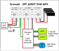
This is the dilemma for me. What happens to Neutral when the generator is replaced by Grid Power?

EDIT: Question answered in post #9, suggesting "DON'T SUPPLEMENT WITH GRID POWER, USE A GENERATOR INSTEAD."
120-240 dilemma WYT.PNG
The diagram is simplified to focus on AC in. AC out is more complicated than shown.
 
Last edited:
Excellent question.
i’m nowhere near a utility pole so I haven’t had to figure that one out. I did follow the guidance suggested by RCinFL (??) and am up and running with generator as shown in the diagram.
Now… configuring the damn thing. The documentation from Growatt is a sadistic joke IMHO. I bought SolarAssistant software and put it on a Raspberry pi… I just plugged it in and IT IS WORKING!
I’m now confident about 80% of the settings. A huge improvement from the bizarro LCD panel.
 
Per code, you cannot connect to grid because you need common neutral from grid neutral to inverter output neutral. All your existing house wiring outlets has their grounding and neutral bonded at main grid breaker panel.

If you common connect grid neutral to inverter output neutral the inverter output transformer will attempt to correct for any grid L1-N and L2-N voltage imbalance which will consume some of inverter output transformer power handling capability. This is same issue with autotransformers.

99% of time there is not enough imbalance on grid to cause significant inverter transformer neutral current. But, if it is significant it can damage inverter. Inverters like Xantrex, Outback, and Magnum monitor the neutral current and will release their connection to grid if it gets too significant of a load on inverter transformer. Low cost low freq inverters like AIMS, Growatt, etc. do not have this neutral current check.

Most all inverters have a temp monitoring of output transformer and will shut down inverter if it gets too hot, but this is slow reacting due to the mass of transformer to heat up. A sudden heavy neutral imbalance can saturate output transformer which will blow out inverter MOSFET drive devices.
 
Last edited:
Believe this is diagram you are looking for. Be careful to only loosen the bottom terminal strip screws. The top screws go to internal inverter wires. Some folks have loosened both and shoved their connecting wire deep into terminal block driving the inverter internal wire out of the terminal block at the top.

View attachment 92882
I have been trying for months to figure out why my solar panels were not showing up on my display. After reading this post, I looked at my internal wiring and that's exactly what happened to my inverter. The internal wires were pushed out from the top screws. I'm up and running now. Thanks @RCinFLA
 
:unsure: I have a question for those electrical engineer types..
Lets talk about 120/240v split phase USA electrical..
say I have a Oven Range stove system that is 120/240v range.. it is wired to the power source receptical with L1, L2, Neutral and Ground.. Now, lets turn on the electric Stove top burners, they are wired on the 120v side and the microwave that is built in also same.
But the Oven is capable of 500 degrees and wired for 240volt. the Max Amp draw of the Oven Stove Range is specificatons are 40-45 amp rating..
When turning on the Oven which is using 240v to provide the power of 40 amps.. I am under the belief that in the split phase system, L1 = 20-25 amp capable 120volt & L2 = same as L1-120v 20-25 amp, the sum total of Amps and Volts available for the Oven is 240v and 40-50 amps.. espcially if you have a Self Cleaning Oven.
Please enlighten me about the Split phase I described above and the total sum is 40-45 amps, or am I seeing it wrong.. that L1 & L2 each are providing 40-45 amps.. this is why when you go to the break box, the Circuit break is 50amp, and when its connected it is pulling of Two seperate Bus bars, L1 and L2. Giving you 50 amp capable but its not pulling 50 amps from each bus bar connection its only pulling around 20-25 amps from each .. Am I seeing this wrong? thanks Ric :rolleyes::)
 
Hello there people more knowledgable than myself!!
Im the proud new owner of a Growatt SPF 6000T DVM-MPV. My decision to buy was based on powering our cabins 120V circuits 1st but having the robust ability to run our 240 V well pump as a bonus. The documentation from Growatt is confusing me... in the "AC Wiring" section of the manual it looks like I can do ONE OR THE OTHER but NOT BOTH. Also when I look at their diagram I find it odd there's not much mention of bonding or grounds... its occurring to me while I type... Did i buy a grey market gizmo that doesn't conform to NEC? Its been 35 years since I wired a house, so my skills are in the tank. Im asking here because Im having a little trouble getting Growatt to respond to my queries ?.
Thanks in advance for assisting old novice, any pointers on this issue truly apreceated!
Cheers
Do you have access to grid at the cabin? If no, it makes things much simpler with the spfxxxxt.
 
:unsure: I have a question for those electrical engineer types..
Lets talk about 120/240v split phase USA electrical..
say I have a Oven Range stove system that is 120/240v range.. it is wired to the power source receptical with L1, L2, Neutral and Ground.. Now, lets turn on the electric Stove top burners, they are wired on the 120v side and the microwave that is built in also same.
But the Oven is capable of 500 degrees and wired for 240volt. the Max Amp draw of the Oven Stove Range is specificatons are 40-45 amp rating..
When turning on the Oven which is using 240v to provide the power of 40 amps.. I am under the belief that in the split phase system, L1 = 20-25 amp capable 120volt & L2 = same as L1-120v 20-25 amp, the sum total of Amps and Volts available for the Oven is 240v and 40-50 amps.. espcially if you have a Self Cleaning Oven.
Please enlighten me about the Split phase I described above and the total sum is 40-45 amps, or am I seeing it wrong.. that L1 & L2 each are providing 40-45 amps.. this is why when you go to the break box, the Circuit break is 50amp, and when its connected it is pulling of Two seperate Bus bars, L1 and L2. Giving you 50 amp capable but its not pulling 50 amps from each bus bar connection its only pulling around 20-25 amps from each .. Am I seeing this wrong? thanks Ric :rolleyes::)
Check your range specs since many run the top burners at 240vAC. There may be a circuit on your range for 120vAC to run the microwave. The 50a breaker and wire requirements come into play to power all the things at once. (your range seems to have a rated amount of 40-45a) Each leg of the 240vAc can provide 50a 120vAC or both legs can supply 50a 240vAC. The power is the same. W=VA.

The fact you see only 20-25a per leg just means that is the load it is drawing. 20a at 120vAC =2400w on each leg, combined legs equals 4800w. Which is 20a at 240vAC.
 
Update, to my understanding.. from Growatt Techs,, as for the SPF6000T split phase 120/240v has a max capable of 25 amps.. for either side of the L1 and L2 with neutral.. so if you have a unit or appliance that requires 30-50 amps,, the Growatt will go to Fault 07 ( Overload) and disengage of the AC output bus.
Summary, L1 and or L2 lines feeds Output will only give 25amps continous, and a few over. but once it hits a demand of 105-110% demand Fault 07 will come on and Output AC will stop.. - Thus I will need to up the SPF6000T to the SPF12000T-DVM which will give me 50amp on L1 or L2, etc.
The idea that L1 would provide 25amp and L2 same for a total 50amp does not work this way.. If I had understood this clearly 3+ years ago, I would have purchased a SPF12000, know then the Range Oven Miele in Self Cleaning Mode draws about 40amps and this is why I get a fault 07.. with eh SPF12000, I would have been good to goe.. Life is a learning experience.. when you stop learning, you're either dumb or dead... Keep Learning and Sharing...
 
Do you have access to grid at the cabin? If no, it makes things much simpler with the spfxxxxt.
No Grid - Kornbread, Generator with 30amp max capable 240V.. but since the Growatt is controlling everything.. it will still cause fault 07, because I need 40-45amp, when you have the program 01 of the Growatt -= UE1, then what happens the Growatt tries to get the Gen to provide the Amps, and even thou it is diesel gen, it bogs the engine down and afriad it will burn the Gen up.. simple fix, have to swap out the SPF6000t for a SPF12000t which can handle 50 amps at 240v.. appreciate the comeback Thanks Ric
 
No Grid - Kornbread, Generator with 30amp max capable 240V.. but since the Growatt is controlling everything.. it will still cause fault 07, because I need 40-45amp, when you have the program 01 of the Growatt -= UE1, then what happens the Growatt tries to get the Gen to provide the Amps, and even thou it is diesel gen, it bogs the engine down and afriad it will burn the Gen up.. simple fix, have to swap out the SPF6000t for a SPF12000t which can handle 50 amps at 240v.. appreciate the comeback Thanks Ric
Good, no gird as that completely eliminates a couple of the spfxxxxt disadvantages 1) in times of imbalance, it can try and balance the street transformer which could cause the growatt's internal transformer to overload, and 2) it is getting dated in that they have very few grid assist/backfeed options.

The good thing, the 6k is good with surges, as is the 12k. There is a 12k for sale in the adds here. Might get a decent deal if you happen to be within driving distance of the seller.
 
Back
Top