diy solar

diy solar

Adding remote on/off to inverter - Help

Newenough

New Member
Joined
Sep 20, 2019
Messages
207
My inverters switch has 3 settings. 2 "ON" positions, On (Power Save Mode), and just On (no power save), and then "OFF". The remote I got has +/- in, +/- out for 2 wires. So I ran the On (no power save) and Off wires into the IN side of the switch and ran new wires from the Out side of the switch to the original On Off wires. Essential placing the switch in the moddle of the 2 wires, nothing difficult here, or so I thought. Connected the inverter back up and it came on by itself (no swith or button pushed) in Power Save On mode only. Cannot turn off with remote either. That wire was also left untouched (dont use that function). Ant ideas on were I went wrong? I also tried swapping the wires from the Out to the In, nothing...
 
Last edited:
The switching unit of the remote control looks like it draws its own power from the input connectors. At a guess I'll say that the switch you see on the inverter isn't switching high current DC, it's only switching signal lines. The load of the switching unit is effectively making it look like the switch in the inverter is in one of its on positions.

Can you draw and post a diagram of how you have things wired up?
 
I was in the shower and figured I wired wrong anyway. And also sure you are correct as well. The switch goes to a connector attached to a pcb. All low current stuff. What I have is a relay "switch". It did not occur to me when I opened up the inverter that I have the wrong thing. Thanks for the input and confermation! Off to Amazon...
 
I plan to take a current reading tomorrow of the draw from the switch. But, does anyone know of a remote switch that can work in a low voltage scenario (self powered maybe)?
 
As equipment gets smarter the common on off switch function is sending command signals to the devices brain. Like on = 500 ohms, off = 1K ohms, standby = 100 ohms. I'm not saying your particular unit is setup this way but we need to stay aware there are new possibilities beyond ON/OFF/STANDBY directly energizing some discrete circuit.
 
Yea my inverter has a pretty weird switch. Turns out this may be the hardest part of the arduino setup I'm doing is figuring out how to get the arduino to properly communicate with the inverter.
 
Desided to keep the wired wall remote and try extending the cable instead. RJ12 has a good run length natively. Depends on the signal strength of the inverters brain at this point. Cheap to test anyway. Thanks for the input as always.
 
You may be looking at an RJ9 connector as at least mine uses this non-registered connector rather than the RJ12. So you will find it does not plug into regular RJ12 female jacks.
 
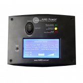
Does your remote look like this or similar ?
41Cm8Fr4aYL._SY300_QL70_.jpg

These are typically RJ11 6 wire straight through but they are limited to no more than 33 feet. My backup inverter uses such and hat limit caused me some angst.
 
REMOTELFscreenon.jpgMine uses an rj12, 6p6c. Its good for 50 feet. I wanted it to stay on the livingroom wall by the entrance, but wont reach now that I moved everything. Thought a remote on off was the solution. it will just be long enough to get to the bedroom. Not a big deal. Just didnt realize even the on/off buttons got all smart and stuff.
 
Does your remote look like this or similar ?
These are typically RJ11 6 wire straight through but they are limited to no more than 33 feet. My backup inverter uses such and hat limit caused me some angst.

You could probably get double that distance with some good twisted pair cat5...maybe?
 
Have you tried that?

Not on this device, don't have one. Not sure why the company screwed around with all types of connectors, if you guys are correct on your rj11,rj12 statements, (the one I see online uses standard rj45 and cat5), but if it's a data connection it should work with a cheap powered network hub or extender. I was a network engineer and had to extend many data connections.
 
Put RJ45's on the ends and run it through a powered network hub/switch near the halfway point. It can be done if you need it bad enough.
My backup inverter is a Yiyen APC-3024 and has a remote similar to the one I displayed from AIMS and no LCD display. it's not data.
My Samlex remote is an EVO-RC-Plus remote which is data but also has RJ45 built in and can go the distance (sadly not ethernet). Although it's not entirely best because the equipment is in a separate building and the inverter itself has no displays on it, just a couple of LED's. It does have rs232/485 Modbus & canbus, so... another subject altogether.
 
Put RJ45's on the ends and run it through a powered network hub/switch near the halfway point. It can be done if you need it bad enough.

DO NOT DO THAT. I recognize that remote, it's made by Sigineer, they're the OEM and everyone else just rebrands their stuff. The sigineer manual for that remote has warnings not to cut it while plugged in because it carries 12v and it'll damage the inverter. Point is Ethernet is not 12v and although it is an RJ45 connector the pins are not wired the same way. If you plug that into a 568A-B wired device it'll cross pairs that aren't meant to go together and you'll fry the inverter. (I know someone that had this issue)
 
Not on this device, don't have one. Not sure why the company screwed around with all types of connectors, if you guys are correct on your rj11,rj12 statements, (the one I see online uses standard rj45 and cat5), but if it's a data connection it should work with a cheap powered network hub or extender. I was a network engineer and had to extend many data connections.
Lol. So was I. MCSE for 20 years and MCT for 10 of that. Novell Netware before even that. Good times but dont miss it in the least. 52 and semi-retired now. Got out 6 years ago. Work 3 days a week at a Sams Club to get out of the house. No...I'm not the old guy at the door ?. My wife makes the big bucks now.
 
Back
Top