diy solar

diy solar

Electrodacus SBMS0 I/O Summary

FilterGuy

Solar Engineering Consultant - EG4 and Consumers
Joined
Nov 26, 2019
Messages
7,932
Location
Los Gatos CA
Folks,
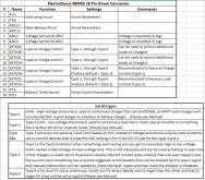
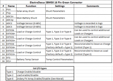
I am working with the Electrodacus SBMS0 for the first time and it took me a while to figure out all the I/O pins on the green connector.
Since the manual is not very clear on some of it, I thought I would share it here:
1605816251777.png
If any of you see any errors or clarifications, please comment. If this looks right to everyone I will post it as a resource
 
Wondering if the other control types would be helpful in the reference. This is copied from Airtime in another thread:

Type 1 (HVD - High voltage disconnect) used to control any charger that can be DSSR20, an MPPT solar charger with remote ON/OFF, a grid charger or a battery to battery charger.
Type 2 (LVD - Low voltage disconnect) used to control any load like in most case an inverter or something like a Victron BP-65 for small DC loads.
Type 3 and 4 are the same as 1 and 2 but based on SOC instead of voltage and should only be used as alarms not to control devices that is what the SOC setting is for in the EXT IO just for this type 3 and 4
Type 5 is for fault conditions when something went wrong and you get to secondary high or low voltage limits named under voltage or over voltage lock. This is not necessary but can be used as backup in case one of the chargers or loads fail to respond to remote ON/OFF control (very unlikely that will ever happen) and the you can have something like a remote triggered circuit breaker than can be tripped by this type 5 signal and manual intervention will be needed to check the fault, repair and then reset the breaker or breakers.
Type 6 is for dual PV setup where you install two PV arrays ideally one 2x larger than the other and that 2x larger PV array will be set as type 6
 
  • Like
Reactions: Dzl
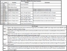
OK, How is this:

1605824073253.png

How sure of you on the type descriptions?

Edit: Changed chart to show all of the Type 5 text
 
I would put it past Dacian. He is always very good about responding to questions on his equipment.
 
This is awesome! good work, the official SBMS documentation could definitely be improved upon and 'filled in' a bit. Dacian has so much accumulated knowledge and wisdom about his devices, but only a small fraction of it makes it into the documentation, and not always in a conceptually clear way. Do you mind if I cross post this to the main SBMS megathread.

Also what do you know of ADC2 and 3, from the little bit I remember hearing, I vaguely recall that these might be unused/unexposed-in-ui sensors that are present but that the default config and the UI does not do anything with but could be utilized for something. Is that your understanding?
 
Do you mind if I cross post this to the main SBMS megathread.
Go for it!!! (I also put the chart in the resource section)

Also what do you know of ADC2 and 3
This is what Dacus told me in an email:

The ADC2 and ADC3 have no specific functionality. They are just voltmeters and will
measure any voltage up to 60V DC and display on page 1 monitoring and will also be
stored together with other values so they are there if you want to measure something
specific and have it logged.


I can see where this would be useful in trying to track down an intermittent problem.
 
I just added the ADC2 and ADC3 description to the resource.

View attachment 28034
I am no expert on the SBMS0, so pls don't flame me.

I purchased one recently but do not have cells yet to test its functions.

Based on Dacian response in a public forum post - I think that perhaps Type 1 has the ability to do more that just HVD charging. Seems that it can be set to do a full charge based on cell voltage and then revert to SOC charging after that (until midnight of the same day, when the cycle repeats.) This feature presumably to save the cells from being full all the time.
I am still learning myself....and I don't know about what you describe. Could you point me to what you are referring to?
 

Attachments

  • Electrodacus Solar Electrical Diagram XV.pdf
    285.3 KB · Views: 53
@FilterGuy Nice, I been working on a system for sometime and needed some confirmation and information this is perfect-thank you!

I attached my plans so let me know what you think if you would.
I did not go over it with a fine tooth comb but as I scanned it only one thing jumped out at me: What is the purpose of the PC817 opto-coupler board? It looks like you are just trying to use it to control multiple items on ExtIO4 ( DSSR20s and the MultiPlus) and ExtIO5 (Orian and Battery-Protect).

I am pretty sure the Orion and Battery protect can both be controlled by a 24 volt nominal signal. Just put 24V on ExtIO5+ through a 470-1Kohm resistor and then use ExtIO5- to drive the pins on the Orion and the Battery protect. (I am pretty sure the Orion and the battery protect controls are pretty high impedence so they need very little current. However, you need to measure the current the draw before you hook them directly to the SBMS0. It can only handle 50mA)

ExtIO4 may still need a circuit to split them out but I don't know if the PC817 will work for you.

1) The input circuit is is rated for 3.6-24V but your system voltage is going to range from ~24-29V. I would be worried about burning out the inputs.
2) I can't tell enough about the PC817 outputs to say for sure if it will drive the DSSR20s, but I *think* if you jumper it to pull down and put the DSSR across 'G' and 'O' it will work. (You might have to try switching the leads to make it work if it is not a bi-directional path on the output. The same comments apply to driving the MultiPlus.

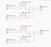
Note: I have looked a little for multi-channel isolator boards with better input voltages but have not found one. I ended up building this:

1608284161973.png
Each of the inputs is split out into 2 outputs through a 2A DC-DC SSR. It was designed for the Chargery but could be used for the electrodacus.
The input is 3-32V and the output is 3-60V/2A.

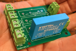
I even had some PC boards made for the design.

1608284782286.png
I am waiting on parts to test it. Once I have it proved out I will write up a resource about it.

BTW: I see you found my inverter disconnect and I/O summary resources. :) At the end of the I/O sumary are a couple of sample designs that you might find interesting.
 
I even had some PC boards made for the design.

View attachment 30601
I am waiting on parts to test it. Once I have it proved out I will write up a resource about it.
@FilterGuy
Love that board. It would be absolutely perfect for my needs.
I've never tried to do any electronics before, but this encourages me to have a go....so thanks for that. (y)

Where did you get the pc boards made for that design...would you have a link?
 
@FilterGuy
Love that board. It would be absolutely perfect for my needs.
I've never tried to do any electronics before, but this encourages me to have a go....so thanks for that. (y)

Where did you get the pc boards made for that design...would you have a link?

What are your needs?

That SSR is just good for 2A, has 0.75 ohm ON resistance, and 15 mA input current.

A relay might be better for switching small currents. I use Takamisawa RY12W-K relays. It's good for 1A and about 14 mA input current.
 
Hi Cal, thanks for the input. I'm simply adding it to the charge/discharge relays of my Chargery unit, which in turn is then connected to the remote on/off switching of my victron units. (might use the aux port on the inverter)
I already have the Kyotto ssr's, but rather than simply soldering wires to the pins, i thought it would be much neater done on a board. (i suppose in hindsight though, i am just adding in resistance with the screw connectors....so i might just go back to plan A....lol).

I did think though, that at 12v input, the current would only be around 8mA, going by the datasheet characteristic curves?
 
Last edited:
I did not go over it with a fine tooth comb but as I scanned it only one thing jumped out at me: What is the purpose of the PC817 opto-coupler board? It looks like you are just trying to use it to control multiple items on ExtIO4 ( DSSR20s and the MultiPlus) and ExtIO5 (Orian and Battery-Protect).

I am pretty sure the Orion and Battery protect can both be controlled by a 24 volt nominal signal. Just put 24V on ExtIO5+ through a 470-1Kohm resistor and then use ExtIO5- to drive the pins on the Orion and the Battery protect. (I am pretty sure the Orion and the battery protect controls are pretty high impedence so they need very little current. However, you need to measure the current the draw before you hook them directly to the SBMS0. It can only handle 50mA)

ExtIO4 may still need a circuit to split them out but I don't know if the PC817 will work for you.

1) The input circuit is is rated for 3.6-24V but your system voltage is going to range from ~24-29V. I would be worried about burning out the inputs.
2) I can't tell enough about the PC817 outputs to say for sure if it will drive the DSSR20s, but I *think* if you jumper it to pull down and put the DSSR across 'G' and 'O' it will work. (You might have to try switching the leads to make it work if it is not a bi-directional path on the output. The same comments apply to driving the MultiPlus.

Note: I have looked a little for multi-channel isolator boards with better input voltages but have not found one. I ended up building this:

View attachment 30600
Each of the inputs is split out into 2 outputs through a 2A DC-DC SSR. It was designed for the Chargery but could be used for the electrodacus.
The input is 3-32V and the output is 3-60V/2A.

I even had some PC boards made for the design.

View attachment 30601
I am waiting on parts to test it. Once I have it proved out I will write up a resource about it.

BTW: I see you found my inverter disconnect and I/O summary resources. :) At the end of the I/O sumary are a couple of sample designs that you might find interesting.
The PC817 opto-coupler board came into my design after a couple of back and forth discussions with Dacian. A little history-my first choice for inverter charger was the Sungold (I'm cheap-lol).

Dacian wrote: "The SBMS0 will be connected to inverter/charger but it needs to have two connection one for the inverter controlled by SBMS0 EXT IO3 set as type 2 and the other for the charger part that will need to be separately controlled by EXT IO4 set as type 1
It seems you used all 4 of the EXT IOx so you will need to multiply them externally by adding more optoisolators in order to control all your charge sources and all loads."

After that I decided to go with Victron Multiplus, and ask Dacian if PC817 opto-coupler board would work since I seen others using it on group.google and ElectroDacus.com. I also sent him my diagram which he said should work.

He wrote:"Yes, that board will work as others have used the same one. Just remove the red jumpers and connect as you showed in the diagram"

Now, to your questions and comments: short answer because Dacian recommend it and reviewed and said that it would work. I don't have the technical expertise as you and Dacian have. I would just need to pose your questions/concerns to Dacian.

If others have used it for 24 Volt systems you are probably OK. I was just going by the voltage rating I saw when I looked it up. All of these types of electronics can be driven at higher voltage than the spec.... but you are eating into the design margin. I tend to avoid doing that.

Dacian's message confirms what I said about the outputs.
 
What are your needs?

That SSR is just good for 2A, has 0.75 ohm ON resistance, and 15 mA input current.

A relay might be better for switching small currents. I use Takamisawa RY12W-K relays. It's good for 1A and about 14 mA input current.
For switching low current signals, either should work fine with a Chargery.
 
@FilterGuy
Love that board. It would be absolutely perfect for my needs.
I've never tried to do any electronics before, but this encourages me to have a go....so thanks for that. (y)

Where did you get the pc boards made for that design...would you have a link?
The company that made the boards is JLCPCB. The Software I used to design the circuit and the board is EasyEDA. You can order the boards right from the SW.
 
The company that made the boards is JLCPCB. The Software I used to design the circuit and the board is EasyEDA. You can order the boards right from the SW.
Think i will have a go at making your design from some thin polycarbonate sheeting i have...really just need to support the pins. A few connectors and some cabling and i'm good....lol.
 
Back
Top