diy solar

diy solar

Growatt 5000es - Simple protection from lost neutral?

justinjja

New Member
Joined
Jun 12, 2021
Messages
41
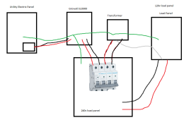
Was thinking about this on the way to work today...
1643131144588.png

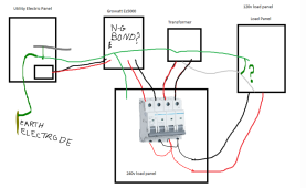
I think a setup like this gives you reasonably good protection from a floating neutral with a 240v inverter?
No flipping / tripping of a breaker results in a floating neutral. (tripping the transformer breaker cuts all power to the load panels)
You could still have a failed transformer or lose wire, but a regular utility connected house is still susceptible to either of those failure modes.

Assuming this does make sense, anyone know where to get quad common-trip breakers?
Do any manufactures let you "mix and match" single breakers and connect them for common trip?
Otherwise it might be impossible to find a quad breaker with 2 higher current breakers for the inverters and 2 lower current breakers for the transformer.
 

Attachments

  • 1643130644885.png
    1643130644885.png
    64.6 KB · Views: 4
Was thinking about this on the way to work today...

View attachment 81193

I think a setup like this gives you reasonably good protection from a floating neutral with a 240v inverter?
No flipping / tripping of a breaker results in a floating neutral. (tripping the transformer breaker cuts all power to the load panels)
You could still have a failed transformer or lose wire, but a regular utility connected house is still susceptible to either of those failure modes.

Assuming this does make sense, anyone know where to get quad common-trip breakers?
Do any manufactures let you "mix and match" single breakers and connect them for common trip?
Otherwise it might be impossible to find a quad breaker with 2 higher current breakers for the inverters and 2 lower current breakers for the transformer.
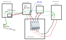
The diagram seems to be incomplete. Is this what it is supposed to be:
1643135209591.png
Changes/questions:
1) the load panel side of the quad breaker is routed to the load panel...???
2) In North America, the Utility panel would have an N-G bond.
3) In North America, there will be a grounding electrode connected to the Utility Panel Ground.
2) Would you put an N-G bond in the load panel? In this diagram, it would be needed in order to have a low impedance path for clearing faults.
3) What does the ES 5000 do for N-G bonding? The answer needs to be that it does nothing.... but we have learned that on Non-North American models when in invert mode it bonds Neutral to the ground. This ends up looking like this:

1643135500746.png
This puts both neutral and one side of the 240 both tied to ground...... that is a major problem
 
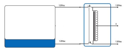
BTW: I assume the design is trying to do this but isolate both sides of the transformer
1643136411790.png
 
Once the input is isolated the auto transformer is de-energized so I don't understand the purpose of disconnecting the output.
 
Was thinking about this on the way to work today...

View attachment 81193

I think a setup like this gives you reasonably good protection from a floating neutral with a 240v inverter?
No flipping / tripping of a breaker results in a floating neutral. (tripping the transformer breaker cuts all power to the load panels)
You could still have a failed transformer or lose wire, but a regular utility connected house is still susceptible to either of those failure modes.

Assuming this does make sense, anyone know where to get quad common-trip breakers?
Do any manufactures let you "mix and match" single breakers and connect them for common trip?
Otherwise it might be impossible to find a quad breaker with 2 higher current breakers for the inverters and 2 lower current breakers for the transformer.
Watch all of this first.
 
Do any manufactures let you "mix and match" single breakers and connect them for common trip?
At least Square D allowes you to gang breakers. They sell kits with pins and spacers that go into the little holes in the breakers and gang them together. However, I do not know how many they support ganging together.

Two ganged together: Yes.
Three Ganged together: Probably (Think 3 phase).
4 Ganged together: I don't know. There is not a big call for that so they may not.
 
All you need is a 2 gang breaker on the output of the inverter before it hit's the transformer and your 120v loads are safe.
Problem #1 solved. I don't know why we are having a hard time with this ???
OK lets solve the other 3 problems.
1. Grounding of all metal enclosures.
2. Current flow back to PoCo transformer with unbalanced loads.
3. Why is the 5000ES being messed with to make it "work" How and is it actually safe.
 
At least Square D allowes you to gang breakers. They sell kits with pins and spacers that go into the little holes in the breakers and gang them together. However, I do not know how many they support ganging together.

Two ganged together: Yes.
Three Ganged together: Probably (Think 3 phase).
4 Ganged together: I don't know. There is not a big call for that so they may not.
Go to 10 min mark of Ian's video for the double gang breaker tripping.
 
My conclusion in all of this is that Auto-transformers requires deep knowledge and understanding that most of us don't have...... Many don't understand grounding and bonding to start with.... throw in an autotransformer and it is a dangerous mix.
 
Was thinking about this on the way to work today...

View attachment 81193

I think a setup like this gives you reasonably good protection from a floating neutral with a 240v inverter?
No flipping / tripping of a breaker results in a floating neutral. (tripping the transformer breaker cuts all power to the load panels)
You could still have a failed transformer or lose wire, but a regular utility connected house is still susceptible to either of those failure modes.

Assuming this does make sense, anyone know where to get quad common-trip breakers?
Do any manufactures let you "mix and match" single breakers and connect them for common trip?
Otherwise it might be impossible to find a quad breaker with 2 higher current breakers for the inverters and 2 lower current breakers for the transformer.
Yes having the breakers on the Inverter 240V output tied with a breaker bar "Or 4 gang" to the Auto Transformer breaker "as pictured in your diagram" should keep the loads from ever seeing 240v due to an autotransformer trip.
It doesn't solve the issue with grid AC Pass Thru though. I would not do AC Pass Thru with an Autotransformer in use. It will try to balance the load for everything between you and the Utilities Split Phase transformer that feeds you. Might be more than you bargained for.
Oh Interesting I forgot about that aspect, more fun stuff to thing about on my drive home!
Edit... wait would it?

I believe the correct way to wire this is with a single gnd-neutral bond in the utility electric panel.
Then lets say the utility is running 110/130 on it's phases.
In my 120v load panel would have 120v and the ground would be sitting at 10v,
But is that a problem?
I don't think there is a current path from grid neutral to my neutral unless I bonded gnd and neutral twice.

I should have added, this is a "USA model" es5000 or whatever signature solar is selling with no ground-neutral bonding.
 
Last edited:
My conclusion in all of this is that Auto-transformers requires deep knowledge and understanding that most of us don't have...... Many don't understand grounding and bonding to start with.... throw in an autotransformer and it is a dangerous mix.
Although we do not have this requirement in ZA , I still maintain that all will be better off with an isolation transformer. Auto transformers are dangerous !
 
I believe the correct way to wire this is with a single gnd-neutral bond in the utility electric panel.
Then lets say the utility is running 110/130 on it's phases.
In my 120v load panel would have 120v and the ground would be sitting at 10v,
But is that a problem?
I don't think there is a current path from grid neutral to my neutral unless I bonded gnd and neutral twice.

I should have added, this is a "USA model" es5000 or whatever signature solar is selling with no ground-neutral bonding.
That's ANOTHER potential issue you are describing "multiple grounds". You just want one common ground. Bonding only in the panel not any equipment.

The problem I'm describing doesn't involve the ground, it involves the neutral and what happens if there is a load difference between L1 and L2 with your autotransformer hooked up. It will carry part/all of the imbalance current, like it is designed to do. The issue with Grid Pass Thru is it will provide this service for everything on both sides of the inverter "pass thru". You don't want the autotransformer trying to balance L1/L2 on the utility side of the inverter.
 
Last edited:
That's ANOTHER potential issue you are describing "multiple grounds". You just want one common ground. Bonding only in the panel not any equipment.

The problem I'm describing doesn't involve the ground, it involves the neutral and what happens if there is a load difference between L1 and L2 with your autotransformer hooked up. It will carry part/all of the imbalance current, like it is designed to do. The issue with Grid Pass Thru is it will provide this service for everything on both sides of the inverter "pass thru". You don't want the autotransformer trying to balance L1/L2 on the utility side of the inverter.
Trying to understand... please bear with me.

Ok so ignoring ground for now.

L1 is 110v to grid neutral and L2 is 130v to grid neutral.
The inverter and autotransformer only see 240v (or less if the utility is out of phase)
How would it try to balance the grid side when the neutral's are disconnected between the grid side and my load panel?
 

Watch Ian's video starting at 1 min. Circulating Current is what I'm referring too. He does a better job explaining than I am in typing.

I may have miss spoke in your case, as your inverter doesn't have a Neutral, but rather this current will flow on the bonded grounds. Remember everything should have a common ground, not a separate ground "he talks about this in point 3", so your main panel "utility" and "inverter panel" should have a common ground..
 
But you shouldn't connect your transformer neutral to utility neutral like he has in his drawing.
Still watching...

Ya that whole section at 1 min makes no sense.
You have a single ground, and 2 separate neutrals and have no problems.
Utility Neutral is connected to GND, Transformer Neutral is not.
 
Last edited:
He isn't connecting the neutrals, they are bonded in the Panels to the COMMON ground.
 
Right I'm suggesting you don't bond the transformer neutral to ground.
Is there something wrong with that?
 
Back
Top