diy solar

diy solar

Help wiring a 3 Position 12 terminal Changeover rotary switch

veggiemate

New Member
Joined
Oct 21, 2022
Messages
7
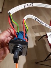
Hello everyone.I've purchased a 3 position (12 terminals) changeover switch and wish to connect my inverter and the mains connection in my caravan (Australia). changeover switch.jpg
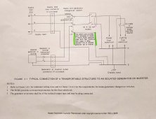
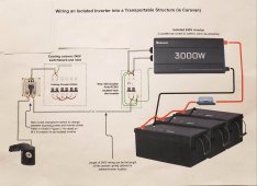
The changeover switch connections are a little different in that I need to include a MEN link as the Renogy inverter doesn't have an earth to neutral internal link (isolated). This is required in order for the RCBO after the inverter to work. Take a look at the next diagram to see what I mean:
326530973_1189456975263232_2947633748712762394_n.jpg

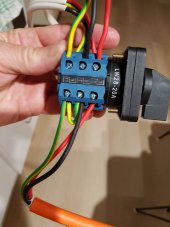
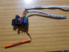
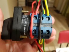
I'm unsure as to how to make the necessary connections. I note in another post and on a youtube video, of the requirement to install a jumper link between the load terminals 2 - 4 and 6 - 8. I did this but it immediately made both number I and 2 switch positions live (as per a continuity test).
I've already made a dummy setup for testing purposes but only running continuity testing at this point.
Can anyone shed some light on what I need to do?
324971120_1334177457360400_4104597320727875846_n.jpg
323703647_620933609843032_683116012762650012_n.jpg
326596665_1838401549875596_7328954845464354624_n.jpg
325914208_693974668879974_8867981120752229904_n.jpg
 
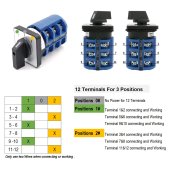
The mains should be 1-5-9, the inverter on 3-7-11. The caravan will be 2-6-10, along with a 2-4 jumper, 6-8 jumper and 10-12 jumper. This takes the 3 caravan wires and switches them between mains-off-inverter. As for the MEN, you can make that bond at the RCBO.
 
324391330_920065848987231_2044305046368237615_n.jpg
 

Attachments

  • 324391330_920065848987231_2044305046368237615_n.jpg
    324391330_920065848987231_2044305046368237615_n.jpg
    212 KB · Views: 106
Last edited:
The mains should be 1-5-9, the inverter on 3-7-11. The caravan will be 2-6-10, along with a 2-4 jumper, 6-8 jumper and 10-12 jumper. This takes the 3 caravan wires and switches them between mains-off-inverter. As for the MEN, you can make that bond at the RCBO.
Thanks for your response TacomaJoe....much appreciated. I already had those connections done except for the 10-12 earth jumper as I was a little unsure about the impact of the MEN bond (jumper) that I had made between 7-11. In Australia, it's a requirement that the MEN bond be created at the switch rather than at the RCBO as per the following diagram: So with this in mind, is my MEN bond between 7-11 correct (refer the last pic)?
324391330_920065848987231_2044305046368237615_n.jpg
 
The 7-11 jumper is correct. The 10-12 jumper is not needed. 9 and 10 should be empty.
 
How good is it that you can ask this question and get a sensible answer?

If this was asked in an Australian forum you’ll be told you will burn down your house and caravan and have no insurance by just daring to think of installing that switch!
 
How good is it that you can ask this question and get a sensible answer?

If this was asked in an Australian forum you’ll be told you will burn down your house and caravan and have no insurance by just daring to think of installing that switch!
Yeah, I know. It's great isn't it :)
 
The 7-11 jumper is correct. The 10-12 jumper is not needed. 9 and 10 should be empty.
Thanks again TacomaJoe. That makes sense. However, the final issue I have is that when I have power running to either mains or inverter switch terminals (setup a 12v battery to test), both positions 1 & 2 and the load are live at the same time!? Am I missing something here? I thought that when one side was activated, the other side is supposed to be isolated.... otherwise, you would have a situation where both the mains and inverter would feed into one another if both were activated at the same time.
Any further thoughts? Maybe I have a faulty switch?
 
Last edited:
In position 1 the RCBO will get power from the mains when contact pairs 1-2 and 5-6 are closed. In position 2 the RCBO will get power from the inverter when contact pairs 3-4 and 7-8 are closed (then run through the 2-4 and 6-8 wire jumpers). In the off position, your mains power is sitting on 1 and 5 and the inverter power is on 3 and 7 but nothing is connecting to those terminals. The switch takes 2-4-10 and connects them to 1-5-9 (in position 1) or connects to 3-7-11 in position 2. The switch never connects 1 and 3 together or 5 and 7 together.
 
In position 1 the RCBO will get power from the mains when contact pairs 1-2 and 5-6 are closed. In position 2 the RCBO will get power from the inverter when contact pairs 3-4 and 7-8 are closed (then run through the 2-4 and 6-8 wire jumpers). In the off position, your mains power is sitting on 1 and 5 and the inverter power is on 3 and 7 but nothing is connecting to those terminals. The switch takes 2-4-10 and connects them to 1-5-9 (in position 1) or connects to 3-7-11 in position 2. The switch never connects 1 and 3 together or 5 and 7 together.
Well...Iooks like I've got things sorted. When I first started researching how to correctly wire this particular switch there were only a couple of youtube videos demonstrating connections for 8 terminal changeover switches but none for 12 terminal switches. They indicated that jumpers should be set between 2-4 and 6-8 terminals and this is what I did thinking it should be the same for my switch. Turns out they should be set on the other side between 1-3 and 5-7 for this particular 12 terminal switch. This explains why I was experiencing simultaneously live connections in any position.
Of course I then had to change over the other connections. So the inverter connections are now set at 4 & 8 and the Mains connections are set at 2 & 6. It's now working as it should be :) Dunno if they are manufactured differently for specific country regulations. Maybe someone more knowledgeable could explain.
Shame they don't include instructions with the switch.
Thanks TocomaJoe in helping me thrash this out over a few days.
 
Last edited:
Hello everyone.I've purchased a 3 position (12 terminals) changeover switch and wish to connect my inverter and the mains connection in my caravan (Australia). View attachment 131978
The changeover switch connections are a little different in that I need to include a MEN link as the Renogy inverter doesn't have an earth to neutral internal link (isolated). This is required in order for the RCBO after the inverter to work. Take a look at the next diagram to see what I mean:
View attachment 131981

I'm unsure as to how to make the necessary connections. I note in another post and on a youtube video, of the requirement to install a jumper link between the load terminals 2 - 4 and 6 - 8. I did this but it immediately made both number I and 2 switch positions live (as per a continuity test).
I've already made a dummy setup for testing purposes but only running continuity testing at this point.
Can anyone shed some light on what I need to do?
View attachment 131983
View attachment 131989
View attachment 131990
View attachment 131991
Hey mate I’ve just got a hold of what looks to be the same changeover switch (from sparkydirect) and am doing the same as you, are you by any chance using the renogy 3000w inverter charger? If so can you still utilise the charging function?

Im hoping to have the changover switch in place like you have done, but when connected to mains also allowing mains power to the input side of the inverter to allow charging of the batteries if that makes sense.
Would it be as simple as running the mains connection from the changeover to the input side of the inverter/charger and having the output of the inverter/charger to what you have done to the changover switch?
Something like the attached image

Any help’s appreciated
 

Attachments

  • Untitled design.jpeg
    Untitled design.jpeg
    211.9 KB · Views: 9
Last edited:
Check your inverter/charger manual for wiring. It may have an automatic transfer switch built in so you wouldn't need the manual one. When the mains are energized the inverter will pass power through to the output and charge the battery. When the mains go down, the inverter takes over and pulls from the battery to keep the output power going.
 
It’s currently hooked up in this way and running fine, but we are finding that when hooked to mains/shore power the renogy unit has to be turned on to pass through power which then constantly cycles the fan and also randomly beeps (short overload error/UPS starting) when our air conditioner cycles on. Which the beep can’t be turned off

Have since found out the UPS starts/beeps at exactly 3000w and our original 15A shore power inlet handles 3600w and trips on 3800+ which runs everything fine.

I know first world problems, but we live in this caravan and these little things are starting to drive us mad hence putting in a changover switch to get rid of these minor inconveniences when connected to mains (and doing away with the ups function)

The Inverter has a good lithium charger built in which I don’t want to lose if I don’t have to, but saying that if it can’t be done then I’ll have to get a stand-alone battery charger.

Hope this helps
 
In my trailer I have a separate inverter and charger, so I don't have the automatic transfer that would be built into the Renogy but I prefer the manual switch anyway. Your sketch wiring diagram will work but I think that you would want some sort of RCB between the mains and the inverter input.
 
In my trailer I have a separate inverter and charger, so I don't have the automatic transfer that would be built into the Renogy but I prefer the manual switch anyway. Your sketch wiring diagram will work but I think that you would want some sort of RCB between the mains and the inverter input.
Thanks mate, makes sense to put an RCB between those, will pick one up and do some testing.

I’m still considering going back to a setup like you mentioned as I’ve done this before and it was trouble free and easy to work with, not to mention a lot lighter than the current inverter/charger.

Also it’s always in the back of my mind that something happens to mains and the auto transfer happens while I’m out and drains my batteries ?
 
Last edited:
Back
Top