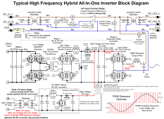
In attached diagram, note the path from PV inputs to HV DC bus and AC generating H-bridge PWM switching.
The AC PWM H-bridge effectively flips the floating HV DC supply polarity at the line frequency rate. When AC output neutral is grounded, this HV DC polarity relative to neutral-ground will flip polarity at the AC line frequency rate due to the PWM H-bridge.
The optional HV DC to DC converter between PV SCC output and HV DC bus is primarily to provide DC voltage step down for 120vac inverters to allow PV SCC to accept up to 500 vdc PV array voltage.
120 vac HF inverters that do not have the optional DC-DC converter in PV path only allow PV DC voltage up to about 200 vdc to prevent PV SCC boost output from exceeding HV DC bus voltage. You can check inverter PV max voltage specs. These HF inverters also have no isolation between AC H-bridge and PV SCC circuitry, so PV input terminals ride on top of flipping HV DC bus polarity when AC output neutral is grounded.
SolArk and Deye split phase 240/120vac HF inverters include two series connected 120 vac inverter H-bridge modules and have two separate, isolated 250 vdc HV DC buses for each 120vac inverter module. They have the optional DC-DC converter to step down the PV DC voltage from 500vdc to two separate 250 vdc outputs so the common PV power can be shared between the two independent and isolated HV DC buses. Since the two HV DC buses must be isolated it also means the PV SCC output ground reference must be isolated from the two HV DC buses. The extra DC-DC voltage down converter also provides this input to output isolation with opto-isolated voltage feedback control path.
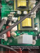
Several 120vac HF inverters, including EG4 6500, allow PV inputs up to 500 vdc. This requires the optional DC to DC voltage down converter to supply the 250 vdc internal HV DC bus feeding the 120 vac sinewave generating PWM H-bridge. In this case the DC-to-DC converter does not have to provide PV input to HV DC bus ground reference isolation, although it would be very simple to do with opto-isolators in the DC-DC converter's voltage feedback control loop. This would be similar to how the battery to HV DC converter works, which has battery ground reference to HV DC bus isolation.
The optional additional DC to DC voltage down converter also adds a couple of percent efficiency loss in PV power path.


