diy solar

diy solar

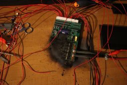
My jk bms just exploded after i enabled charge, and i dont know why. See pictures. i need help

Aridom82

Learning addict
Joined
Aug 3, 2022
Messages
489
Location
Piedmont (Italy)
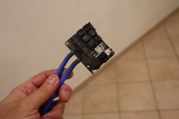
So this just happened:IMG_1105.JPG
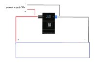
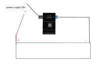
This is the connection diagram i had:
wtf.jpg
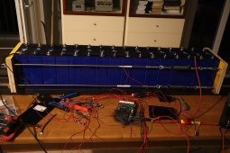
The red wires were connected properly, the bms was up and running, i had connected the power supply to start charging the batteries and after i enabled charge via the app the bms exploded like fireworks. I hope my cells are still ok. I dont know what happenedIMG_1106.JPG
 
Yup. Blue and Black only go to the negatives. That was heck of a short you created to make it go boom like that,. I'd be proud of the carnage and appreciative of the amount of power on tap. Replace the BMS and wire correctly.

Also, I really like your take on the compression springs, I've never seen that setup before and plan to copy it in my pack redesigns, seems way to easy.
Is was like fireworks, it took 5 minutes for my heart to slow down.
The traction springs are the best way i have found for compression. You can calculate how much force you are putting just by measuring how much the spring has elongated with a caliper. To achieve the 300kgf with 4 springs look for 4-5 mm diameter wire spring when you buy, look for the specs.
I am putting together a prototype pack. Today was test day for the bms system... what can i say? The road to success is paved by failure
You’ll know what not to do.
 
That little push button on your desk that came with it should have been connected to one of the connectors on the JK BMS and hold it down for a couple seconds. That is how it turns on.
I tried and didn't work. I was frustrated with the red wires connector, it wouldnt fit, it had pushed a pin inside the bms and i had to fix it, etc.
Turns out that in my anger i forgot to connect the last red wire to the positive end of the pack. What got me confused is that when you short circuit the bms it turns on ok, until you enable charge. Then it goes kaboom.
I think i have anger management issues. :ROFLMAO:
 
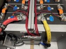
On top of what others have told you about the main leads, it appears that you have the balance connector plugged into the bms. This shouldn’t be plugged in until all the leads are connected to the cells then verified in sequential voltage steps. The black balance leads goes to the most negative. Notice that the most positive has two red wires to it. Example, if you have a 16 cell then the sixteenth red wire is connected to the most positive AND the last red wire in the plug. The other wires between are not used but made safe so they are isolated (snip off ends and dip in shoe goop). The two blue heavy cables go to the the most negative of the battery(where the little black balance lead is). The two heavy black leads are to your negative load, but you don’t have to have this connected to start, however it would be wise to make it safe(wrap temporarily tape around it). Once you have those connections made and verified with the manufacturer’s diagram you may finally plug the balance connectors in. Observe the little ribs on the connectors for the right orientation. Now the start button should work. If you have to remove the connectors, don’t tug the leads, work the two ears at each end evenly . IMG_0891.jpeg
 
Last edited:
What got me confused is that when you short circuit the bms it turns on ok, until you enable charge. Then it goes kaboom.
I don’t short to start, I use a multi meter with a good battery in it, set at diode test. The negative test lead to the big black wires and the red test lead to the big blue leads after a few seconds it’ll start. If anything is connected to the battery (parallel battery, charger or inverter) the multi meter doesn’t have the current to do this). I leave the disconnect open to start). Once it’s started, then you can review the settings. Chemistry first, cell count then the rest. Once that’s done you can enable charge/ discharge, pre charge your load ( inverter and/or charger) and finally close the breaker/disconnect.
 
Last edited:
I don’t short to start, I use a multi meter with a good battery in it, set at diode test. The negative test lead to the big blue wires and the red test lead to the big black leads after a few seconds it’ll start. If anything is connected to the battery (parallel battery, charger or inverter) the multi meter doesn’t have the current to do this). I leave the disconnect open to start). Once it’s started, then you can review the settings. Chemistry first, cell count then the rest. Once that’s done you can enable charge/ discharge, pre charge your load ( inverter and/or charger) and finally close the breaker/disconnect.
Thanks, this is the much needed information i wish i had at the start
 
I think you need to watch Andy’s “Off grid garage” early JK bms episodes.
i watched some of those, but the guy doesnt show the wiring or the steps to get it done right. He just shows the trouble he had to start the bms.
i dont have the patience to sit through all of his jokes
 
Back
Top