diy solar

diy solar

Cheap mini solar field build

I don't think what SA wrote is going to work. They just don't want to deal with these questions, so they're throwing bs my way.

I do want to remove the power poles someday. Someday, if / when I'm generating enough power but until then, the grid would be my back up.
The Sol-Ark simplified install will work. The only additional thing I have is a cut-off switch at the Meter in order to meet my local code requirements.

The diagrams are "compatible" in that both will get you power from the Grid/Generator/PV/Battery to your load.

What Sol-Ark can't tell you is what your local code requires (how much of the EG4 diagram do you need). Hopefully your electrician knows.

BTW: The EG4 diagrams on post #30 is for "partial home backup". If you want "whole home backup", then your main panel goes where "critical loads subpanel" is, and you eliminate the "main load panel". Also, the "pv interactive system 2 pole disconnect" is internal to the SolArk, so you don't need that (I thought it was internal to the EG4 too, but don't know). If you hit the RSD, it will cut power from the PV, and to the Grid and Loads.

BTW2: if you implement the Partial Home Backup diagram then: 1) Sol-Ark can limit production to home (CT between Meter and Main Panel); and 2) In the event of Grid Down, your main panel will NOT get power from the Sol-Ark (disconnects anything befor the Grid Input to the Sol-Ark).
 
I have a feeling my electrician & his boys are going to be cutting their teeth on my system. He's a master electrician but when I asked about doing an off grid deal, like a couple lv6548's and a manual transfer switch he said I'd need different solar panels. Ah, what?

I'm sure the simplified install will work, I don't doubt that, but it's about what it takes to get to that point that I'm trying to figure out.
I don't have local code.
 
Derating my panel might be the answer I'm looking for.

What do you guys think about this?


"Derating Your MSP for Solar
Next, we’ll go over what it means to derate your MSP.

Replacing Your Main Breaker

Derating your main service breaker means replacing the 200 amp main breaker with one rated for a lower amount (typically 150 or 175 amps). You would do this to increase the amount of solar you can install. By derating the main breaker in our example above, the math comes out to 240 – 175 = 65 amps of solar that you can install."
 
Not having any code enforcement to worry about gives us rural folk a lot of freedom but I want to do this safely.

It looks like I'd need 3/4" emt for my 6 10awg pv wire but 1" pvc. EMT is no good for ground install. Are my only options to do 3/4" emt to 1" pvc, 1" emt to 1" pvc ( in the case that I cannot transition size) or is there something ellse out there I can use that might be better?

 
Derating my panel might be the answer I'm looking for.

What do you guys think about this?


"Derating Your MSP for Solar
Next, we’ll go over what it means to derate your MSP.

Replacing Your Main Breaker

Derating your main service breaker means replacing the 200 amp main breaker with one rated for a lower amount (typically 150 or 175 amps). You would do this to increase the amount of solar you can install. By derating the main breaker in our example above, the math comes out to 240 – 175 = 65 amps of solar that you can install."
That works IF:

1) Can you find a breaker of the right size for the panel you have? You probably won't find it at a big box hardware store but you might find one on line or at a electrical supply house. The challenge will be figuring out what breakers work for what boxes. The documentation for the boxes don't do a very good job of providing info on what main breakers will work or are available for it.

2) Are your actual loads less than the new breaker size? You will be fine as long as you have the PV/battery power coming in, but if there is no battery or PV, all of the power must come through the downsized breaker. Do you know what the peak wattage your house ever sees? You can calculate you peak amps from that. In most cases this won't be an issue but.....
1. Not sure. My electrician said a 4awg wire will not fit in a 175 amp breaker. If so, why then is it written about, for example in the pasted thread I referenced?

2. I don't know.

He hasn't looked over the inverter manuals yet (15k & 18kpv). He did suggest a panel made by Generac(?) which is 200a + a 50a for the generator. The inverters need a 70a breaker though.

I feel like I'm trying to reinvent the wheel. My house is the typical 200a grid-fed house. There must be thousands of hybrid inverts out there running the same way. There should be a straight forward standard way to do this. One thing's for sure, on-grid solar is not diy for most.
 
Got some feedback from the electrician. I'm not sure if this is a reasonable amount. It's just so vague.

" To run a line from that main panel to the inverter then to the sub panel just doing the high voltage.. it would cost $4,800 to install everything. I supply all conduit and or wiring for all high voltage from utility lines."

This is to install either a SA15 or 18kpv and have the grid as a back up (no backfeeding) to the pv's & batteries and I believe to do a feeder tap.
 
I asked to please specify.

He said
"No main breaker or panel replacement needed . Yes we doing a feeder tap . And installing the high ac voltage components and feeding them .It's a 200 amp service re route basically. So it's going to take some time and we cover all wiring for the 200 amp re route"

I asked
"Will you include a manual shut off switch so the inverter can be shut down in the event that the inverter goes down?"

He said
"There is no need for that because the main breaker on the outside meter will have ability to shut the whole system down"

I asked
"Will it be able to shut the whole system down BUT allow us to continue to use the grid?"

He said
"A feeder tap is off the grid so no the whole thing will be down."

Oy vey.
 
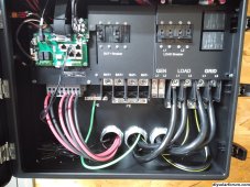
Turns out my neighbor is an electrician and one hellofaguy! He gets the EG4 manual & explained the ac side. It seems so simple now. Apparently, because I've got a 220a breaker on the meter side, he won't install a feeder tap breaker but everything else in the feeder tap diagram in the EG4 manual for "whole home backup with feeder tap" will be installed, including the 2 pole manual transfer switch, the priciest part.
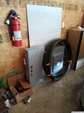
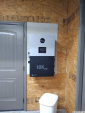
The inverter & other ac side components will be installed outside, right next to the meter and the batteries will be inside in the mudroom, right on the other side of wall.

I bought this

EG4 18KPV Hybrid Inverter System Bundle - 30.72kWH EG4 Lithium Powerwall [BNDL-E0005]


and this

Canadian Solar 12kW Pallet - 400W Mono-crystalline Solar Panel (Black) | CS6R-400MS-HL | Full Pallet (30 Solar Panels)


Kodi at Signature Solar answered every little stupid question I had. Probably about 50 of'em. I'm not interested in electricity or the knowledge thereof and find it all rather boring and challenging to learn but I am completely off grid (other than power) so the ability to not need the power grid is the goal and this stuff is a good start.

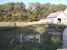
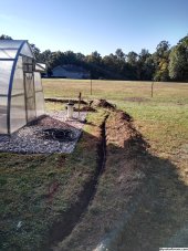
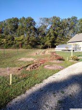
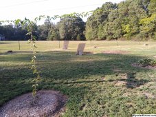
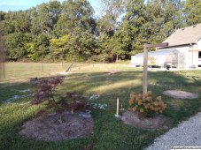
I've decided to relocate the mini field. 4 maples came down & the poly-fence is getting pushed out closer to the property line to fit 2 rows (17 & 13). Damaged one of the hardy kiwi supports. Damn it. Stumps need grinding and I gotta smooth out the land here, but this area will make for a better install. The longest run is 40' shorter than the old location, I don't have to cross the driveway & bore under the sidewalk, more sun here & I can ground the field to the house ground at the meter.

The white line represents where the shadow is cast from the top of the fence. It closely follows solar south. The house is on 5 acres but is built close to the sw corner of the property. It's a large area but the panels will still be pinched in here a bit.
Row 1 is around 100' long and the back row (2) around 80. String 1 on the east side will have 7 pvs in the front row and 3 in the back. String 2 in the middle with 5 & 5 and string 3 ends close to the back of the greenhouse on the west side. Right now, this area get's full sun from 8:30am till around 5pm with string 1 in the sun until 6.

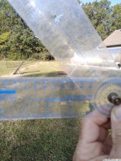
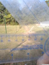
I set this angle finder to 50* which is right around the winter adjustment these panels will be set at. Holding it level, you can see I got the 2nd row lined up well with the angle finder but the first is off a bit. Still, it appears that the panels will experience no shading from each other or the fence when the sun is at it's lowest point of the year. This way suits me rather than attempting to do the math that I do not know how to do. Summer's easy at 14* and I'll probably make both rows adjustable for each season of the year. Each panel will adjust semi-independently of one another.

Apparently, rodents like too chew the wire, not for the soy content but because the hardness is good to sharpen their teeth. I'll contain all of the exposed wire with automotive wire loom and keep an eye on it.

Anyone who's actually read this gibberish and is really in the know about power surge and lightning strikes please tell me, what should I or could I or do to protect these electronics?
IMG_20230919_084639705.jpg

IMG_20230919_084556046.jpg

IMG_20230919_084541545.jpg

IMG_20230919_084426565.jpg

IMG_20230919_084355963.jpg
 
AC side will hopefully be started and completed tomorrow.
IMG_20231017_085359107.jpg

Inverter is going right here and the batteries in the mudroom on the other side of the wall to the right.
IMG_20231017_100833875.jpg

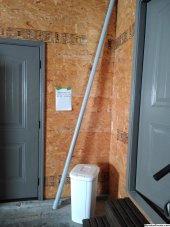
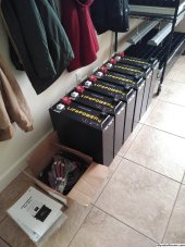
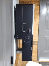
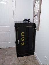
EG4 battery rack will go in this corner. Flat on the floor. No wheels. Conduit through the wall the door is on into the garage. Hopefully I get my battery rack soon.
The breaker panel is behind the artwork.
IMG_20231017_100807285.jpg

I don't want to temporarily install these.
IMG_20231017_085444149.jpg

I believe the manual transfer switch is going right here, between the meter & garage door. It'll be backed up to the inverter .
IMG_20231017_091830652.jpg

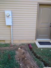
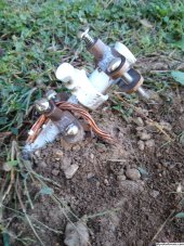
Ground at the meter for the mini solar field.
IMG_20231017_091856591.jpg

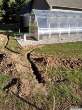
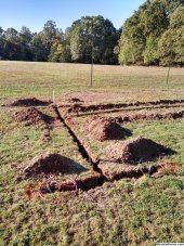
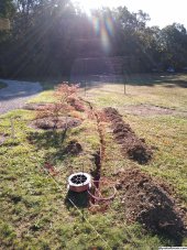
Ditch dug via pick axe.
IMG_20231017_091905032_HDR.jpg

IMG_20231017_091935593_HDR.jpg

IMG_20231017_091920074_HDR.jpg
 

Attachments

  • IMG_20231017_091920074_HDR.jpg
    IMG_20231017_091920074_HDR.jpg
    1.1 MB · Views: 0
+1 For the work man.
Cool to see the project.
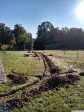
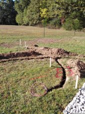
Thank you. It crosses the internet line 4 times, the well pipe & it's power & the grid's power. With all the cross trenches I needed, tree stumps & roots and stuff in the ground, I didn't think a machine would be much help. This is the best location on my multiple acre property.
I threw more pics up for the next guy/gal who might be interested in installing a super-cheap mini solar field.
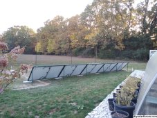
2 rows, 3 strings.
String 1 on the west side with 5 panels in each row.
String 2 in the middle with 5 panels in each row.
String 3 on the east side with 3 panels in the back and 7 panels in the front row.
There's the main that runs from the equipment area on the house out to the 1st, 2nd & 3rd trench crossings. There's 4 crossing total.
The 4th crossing is only an extension to connect the 3 to the 7 as it picks up and returns at crossing #3, so it doesn't feed off the main.
The other 3 either feed or feed and extend the adjacent strings.
This field, minus panels, will end up costing < $1k with over 1/2 the cost attributed to pv wire.
IMG_20231017_092242806.jpg
IMG_20231017_092228283_HDR.jpg
IMG_20231017_092210749_HDR.jpg
IMG_20231017_092154109.jpg
IMG_20231017_092134977.jpg
 
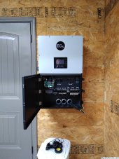
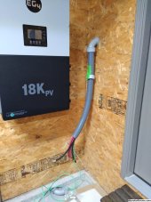
So far a clean and trouble-free install of the EG4 18kpv without all the traditional associated...stuff.
The back of the wall has a bit more going on. Pic's to come for that soon.
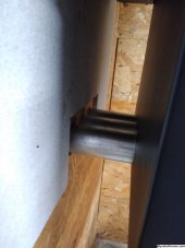
Schlepping this f'n wire through is no joke.
The image on the lcd screen looks absolutely nothing like me. Is this me in 40 years? Will there be another 40 years. I dont think so.
IMG_20231018_212049111.jpg

IMG_20231018_212114296.jpg

IMG_20231018_212148961.jpg
 
So far a clean and trouble-free install of the EG4 18kpv without all the traditional associated...stuff.
The back of the wall has a bit more going on. Pic's to come for that soon.
Schlepping this f'n wire through is no joke.
The image on the lcd screen looks absolutely nothing like me. Is this me in 40 years? Will there be another 40 years. I dont think so.
View attachment 172963

View attachment 172964

View attachment 172965
Really like the through the rear conduit, clean look! Are you concerned about the bend up?
 
Really like the through the rear conduit, clean look! Are you concerned about the bend up?
Thank you.
I'm more concerned about my hands.:ROFLMAO:
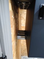
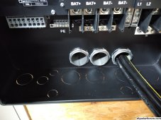
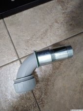
Some threads were damaged on a plastic 90* on the back side of this wall, so the wire in this pic is coming out. This one was more difficult that it looks. Then, we missed installing the cement board behind the inverter which was just sitting there, right against the adjacent wall.
 
Last edited:
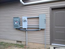
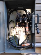
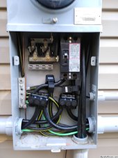
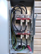
Fused disconnect on left, meter in the middle & manual transfer switch on the right. Manual transfer switch and three 12" nipples replace wire trays and excessive conduit.
Batteries and mini-field up next.

IMG_20231021_181659919.jpg IMG_20231021_165011316.jpg IMG_20231021_165018760.jpg IMG_20231021_165054655.jpg

IMG_20231021_210458220.jpg IMG_20231021_210532541.jpg IMG_20231021_210602989.jpg IMG_20231021_210636684.jpg
 
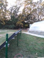
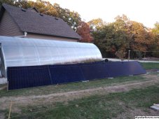
Super-cheap solar field in progress. It's at 45.4ish *, perfect for winter. Adjusting down to 30.4* shouldn't be an issue but down to 14* for the summer will probably be a problem as the posts might cast shadows over the panels. Canadian Solar 400w. These panels are supposed to be a bit more lenient concerning shade, and it certainly wouldn't be much, so I'm willing to give it a go. Worst case I have 45* winter & 30* spring/fall settings and suffer a loss in summer or I scrap the posts and build using unistrut or equivalent but either way, retain the mini solar field in it's current configuration.

I grind off the tabs, hit those areas with some rustoleum spray paint and get them straight and lined up with one another. Most wind comes from the south, and with 75% or more of the panels weight holding down the front end, as well as the zinc coated hardware locking things down up top, I don't these things are going anywhere. They should perform better down here as opposed to the roof.

Got a slight dip between 2 posts when looking straight down the line. I'll work out minor kinks when it's all done. Each panel is level within .1* and each is at 45.4* + or - .1*. Both rows of solar mini field are facing true, solar south.
5 down, 25 to go. So far, I'm a big fan of Signature Solar.

IMG_20231023_174211160.jpg

Panel #2 from left is filthy.
IMG_20231023_174258335.jpg

IMG_20231023_174156112.jpg
 
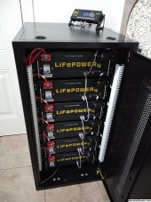
This might be a good reference for those looking to install this rack.
Looks like Sig. Solar / EG4 continues to improve on the battery tower. Still some minor issues from my experience, but it's nice.
There's 4 bolts on each side for each battery and they all line up well.
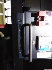
The wheels are beefy, but I didn't use them.
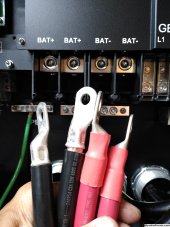
The white wire trays cannot contain the wires without help from Gorilla Tape. You can install the main 4 cables to lay in such a way that you'd think they won't be in the way, but the cables at all connections on the bus bar prevent the top from snapping into place. This part of the system is unfinished for now.
The battery-to-inverter cable is too short, even shorter than the battery cables.

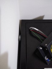
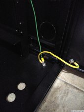
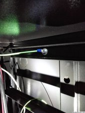
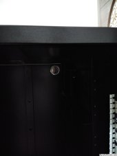
I drilled & installed a grommet for the wires for the communication hub, cut through the back of the unit to run the wires to the inverter in the garage and shared a ground for the hub at the door and placed my own for the ground that needs to go outside to the grounding rod.

IMG_20231026_230740879.jpgIMG_20231026_230721439.jpgIMG_20231026_230643875.jpgIMG_20231026_153023933.jpgIMG_20231026_144924175.jpgIMG_20231026_130744014.jpgIMG_20231026_130713227.jpgIMG_20231026_101052964.jpgIMG_20231026_100452486.jpgIMG_20231027_075246133.jpg
 
Back
Top