diy solar

diy solar

Ferrite ring on battery cables

SeaGal

Photon Sorceress
Joined
Aug 17, 2022
Messages
2,865
Location
UK
My new Solis inverter came with the supplied battery cables pre-wound through a largish (4" outside, 3" inside) diameter ferrite ring - 3 turns of each cable. Didn't have that on the old Solis, so hope the cables will still be long enough to reach the battery disconnector ?

I'm guessing it's for noise suppression as @robby mentioned in this posting...

Is this a new thing that we should all be using on our AIO / Hybrid inverters these days?

Any RF experts out there?
 
The inverter generates a lot of RFI because of relative fast (very short risetime) switching. A lot of current flows during those switching events and as a result a lot of RF power is generated. External ferrite toroids or beads are always an indicator to me that the unit has a hard time meeting FCC part 15 requirements (if that testing is even done at all although it is required for stuff sold in the US).

My fallback is to take a battery powered AM broadcast receiver and evaluate the level of trash generated. You need ro sweep the entire AM band to look for elevated noise and harmonics. If reception below 30MHz or so is important to you, you're probably a ham, and you can do the same thing across the HF bands as well.

The emissions can be conducted along and radiated from wiring, in which case the ferrites can help, or radiated from the unit itself. If radiated from it, there is likely nothing simple that can be done.

On the ferrite front, there are various mixtures of the ferrite material that are optimized for frequency, so you might need several different ferrites to effectively mitigate the conducted noise issues.

The ARRL handbook has a weath of information about thise stuff as well as noise suppression in general. It might be a good resource for you.

Hope this helped!
 
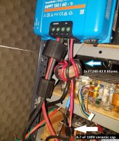
Use it if you can, it can't hurt and only reduces RFI to your radio receivers or your neighbors. Here is what I use to reduce RFI from Victron MPPT 150/60 by 30 dB to my ham radio:
20231024_161503_resized.jpg
 
Use it if you can, it can't hurt and only reduces RFI to your radio receivers or your neighbors. Here is what I use to reduce RFI from Victron MPPT 150/60 by 30 dB to my ham radio:
View attachment 173959
I will be getting some Ferrites in a couple of weeks to try them out.
I am wondering what voltage is coming from your PV, I know it must be below 100Vdc?
It seems to me that having the shaved wire that close together at the Capacitor could possibly generate an arc when using typical 300-400V systems.
I can see your using something to insulate it but it still looks like I can see bare wire at the ground, so not sure if you have the same issue at the positive.
 
Makes sense that Solis did it to meet some RFI requirements (UK in my case).

I will be getting some Ferrites in a couple of weeks to try them out.
Are you going to try them on your dc power leads?
 
I am wondering what voltage is coming from your PV, I know it must be below 100Vdc?
75 Voc. The cap with 4 wires is soldered to small PCB wrapped in tape. It's not necessary but together with the choke it forms an LC filter for residual differential mode RFI while the choke attenuates common mode.
 
Both + & - wound same direction through ferrite should do a lot to block common mode.
Individual ferrites or wound opposite direction, do not expect much suppression of differential mode, because current will saturate it. But they may knock down emissions a little; have heard of such results in testing.
 
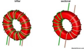
Bifilar versus sectional winding. I prefer bifilar as it has greater common mode attenuation from my testing.

bifilar_vs_sectional2.jpg
 
Good point on saturation! I'm a EE with 40 years under my belt and I'm ashamed it didn't occur to me!!! Guess I'm about ready for the glue factory.
 
I'm a late bloomer in magnetics, beyond simple stuff.

From EEBlog I learned how to measure an inductor BH curve and build LTSpice models.
Useful to elicit behavior and predict performance.
I also learned how to use transformer as amplifier or modulator, but haven't done it with optimal core types.

 
Makes sense that Solis did it to meet some RFI requirements (UK in my case).


Are you going to try them on your dc power leads?
I am so lazy ? I have a spectrum analyzer and I have not even run a test to see if my suspicions are correct and it’s from the MPPTs. Dylan from SA suspects it’s the battery charging system, but I honestly don’t think so.
As soon as I get the Ferrite’s in hand I will make a day of it and find out the source plus hopefully fix it. Stay tuned for updates.
 
Both + & - wound same direction through ferrite should do a lot to block common mode.
They're wound exactly like the 'sectional' image in @AntronX's post above.

I never got into RF and complex electromagnetics - so complex - I vaguely remember learning Maxwell's equations, but a) that was a long time ago and b) not sure I fully understood it then :(

Will need a few more :coffee::coffee::coffee: before attempting a read of the 'Another Inverter Build' thread!
 
Does anyone have a good lead on what type or kind that might be the best for noise attenuation for PV, battery or AC lines ?
I don’t happen to have a spectrum analyzer to see what my LV6548 twins are doing. I do know that my cell phone’s Bluetooth works better if I take a few paces away from them.
 
They're wound exactly like the 'sectional' image in @AntronX's post above.

Field from the two wires cancels, so current drawn by battery doesn't affect it. The wires can act as a loop antenna, so keeping them close even twisted reduces radiated power and reduces inductance. The battery itself will form a loop. I would expect the loop to emit lower frequencies in differential (capacitors absorb higher frequencies), so magnetic field but not higher frequency radio waves.

The choke tries to block common mode current, which would make the length of wire act like a whip antenna. That should attenuate switching and digital frequencies and harmonics.

Does anyone have a good lead on what type or kind that might be the best for noise attenuation for PV, battery or AC lines ?
I don’t happen to have a spectrum analyzer to see what my LV6548 twins are doing. I do know that my cell phone’s Bluetooth works better if I take a few paces away from them.

Interesting that 2.4 GHz Bluetooth is affected. We would expect digital CPU to have some emissions in that range, but not the power conversion equipment. Cell phones use loop antennas (magnetic field, reaches through your hand) rather than whip antenna (voltage field, absorbed by your hand like first generation iPhone.)

Up close, could be near-field magnetic coupling. Lower frequencies, everything is near field, but field strength drops off as r^3 not r^2 like for EM waves. Magnetic fields can be shielded somewhat with steel, more so with mu metal (expensive!) Has to be thick for low frequencies like 60 Hz, but your concerns are likely higher.

There are EMI filter cans to be designed into equipment, typically up to 20A 120/240VAC. Not high enough current for full inverter output. You could get a toroid with frequency curve showing good attenuation in the frequency range you're addressing, and wind wires as shown above.

PV and battery wires, similar use of toroids.

It is best if you have some way to measure the interference or field strength, so you can see how much benefit. Digital radio devices aren't so useful because they frequency hop and change modulation to improve communications. When I was debugging interference with a hand-held blood glucose meter (its readings would vary), I got a "business band" radio and keyed it nearby. Try an AM radio tuned between stations and if static comes and goes when inverter switched on/off, or according to load, then it could be used (for its frequency range.)
 
Back
Top