diy solar

diy solar

Simple home made analog MPPT contoller

the capacitors

Easyeda "JLCPCB assembled" parts available (in stock) for
C2, C4, C5, You recommend 10nF polyester 50v,
Closest I could find there are
10nF polyester 100v. See below, will they be ok?
(I can always buy 10nF polyester 50v separately & solder them in. But the more they can do the better.)

Hopefully I can match the Voltage better with the others.


Box-type metallized polyester film capacitor(Stac…
C24

metallized polyester film, stacked constructionPlastic case(UL94 V-0),Epoxy resin sealingHigh dv/dt ability


Thanks, it will take me a bit to work through your above info.
 
Yes, they will be fine.
Capacitors come in all shapes and sizes, so its a good idea to make the board to fit the capacitors you actually have, or know where to buy something similar if you need more later on.

The 470uF electrolytics are much larger than they really need to be in terms of just capacitance.
The problem is, that anything with much less capacitance, will be smaller physically and have a lower rated ripple current.
We need something that is not going to get hot and fail fairly soon, so bigger is better.
 
Taking the solar voltage first.

If we select for RV1 a potentiometer that can be adjusted between 0 and 50K, the voltage drop across RV1 can be adjusted from 0 to 50 volts.

In my own setup, I am running four nominally 24v panels in series, and from memory the max power voltage is supposed to be about 125v.

So my panels are 38v in series of 3 = max 114v, so I should be able to use the same resistor values as you?
 
Last edited:
The battery voltage adjustment

R8 will always be 5K1 = 5 volts.
RV2 will be 10K giving ten volts of adjustment range.
R4 will be 91K adding 91 volts on top of RV2 and R8.

Minimum battery adjustment range 5v + 0v (pot at minimum) + 91v = 96 volts
Max battery adjustment range 5v + 10v (pot at maximum) + 91v = 106v
So if I use a lithium ion 48v batt. sys.
A quick search indicates max charging voltage of 57.5v (58v).

R8 will always be 5K1 = 5 volts.
RV2 will be 10K giving ten volts of adjustment range.
R4 will be 45K ?? adding 45 volts on top of RV2 and R8.

Minimum battery adjustment range 5v + 0v (pot at minimum) + 45v = 50 volts
Max battery adjustment range 5v + 10v (pot at maximum) + 45v = 58v??
(edit so many #'s in my head should be = 60v, see below)
 
Last edited:
R1 and R9 the two ten ohm resistors can be completely eliminated and replaced with a solid PCB track.
Sometimes resistors are needed in those two positions when optimally tuning a feedback loop.
In this case there was no need for super fast optimally damped feedback.
Its all a lot simpler and more stable by slowing down the feedback.
It still responds extremely fast, compared to a perturb and observe controller.

If you do run into any feedback instability, which is unlikely, just make either (or both) C1 and C3 larger.
A bit of experimentation should fix it.
Not sure on this,
So its not a problem leaving the resistors in, but it may work better with out them?
But they may insure there is no "feedback instability" which is unlikely anyway.
I don't mind having them for insurance, but if it operates better without them.
How would I recognize "feedback instability" ?

You can leave them in, or replace both ten ohm resistors with just a wire shorting link. It makes no difference.

Feedback instability is when the output starts surging up and down continuously.
It over corrects, then swings back too far the other way, then over corrects in the opposite direction.
It just goes totally nuts....
 
Novice Note;
Wasted a lot of time trying to id the voltage for a given capacitor on Easyeda parts search "JLCPCB assembled" function.
The voltage is in code (on the part #), the code index didn't come up on a basic search.
Most common parts available on "JLCPCB assembled" are made in China, (depends on the component) these are mostly new companies ~10 years old etc & are very cheap, 6 cents for the above capacitor, but they do get a bit of criticism.
The supplier below was one of the few that provided an easy code description, see bold.
45
C21
Part number system
The 15 digits part number is formed as follow:
1 2 3 4 5 6 7 8 9 10 11 12 13 14 15

4~5 Digit 4 to 5 D.C. rated voltage

1H=50V 1J=63V 2A=100V 1H=50V 1J=63V 2A=100V
2E=250V 2G=400V 2J=630V 2E=250V 2G=400V 2J=630V
3A=1 000V 3B=1 250V 3A=1 000V 3B=1 250V

Nichicon (Japanese?) data sheets also useful.

I found it quickest to do a general image search for the part (eg with the manufacturer's name & V. F. etc) ebay, alibaba, etc often provide a part #, use the part # on the Easyeda parts search "JLCPCB assembled" function.

This was really helpful, below is just a bit of a novices insights, well worth a read.

Basic vs Extended​


There’s a subset of JLCPCB’s parts that they call Basic parts.All other parts they support are called Extended parts.Basic components have a cost per unit.For each type of Extended component you use, JLCPCB adds $3 to your total cost.If you aren’t careful, this can really add up.For example, if your board needs 10 different types of resistors, and you choose Extended components for these, then you’ll end up paying $30 in fees on top of your per-component and assembly costs.


I found the best way to make sure I was choosing Basic parts was to use JLCPCB’s parts page instead of trying to do it entirely through the Library.In EasyEDA’s Library pane, you can filter for JLCPCB Assembled components, and sort by the SMT Type column, but I found that this was sometimes out of sync with JLCPCB’s parts database, so you may not find parts that JLCPCB actually has, or they may tell you something is Extended when it’s actually Basic.To avoid that, just go to the JLCPCB parts page and browse or search for what you’re looking for, then filter for Basic Parts.
 
Last edited:
Either 1H (50v) or 1J (63v) would be the most appropriate.
Higher voltages would work, but they will be larger, and probably cost more.
Unfortunately they didn't stock those, just the 100v (6 cents each I think) & others.


"So my panels are 38v in series of 3 = max 114v, so I should be able to use the same resistor values as you?"
 
There are some 250uH 20 amp dimmer chokes advertised on e-bay right now that might be ideal.
Would this work?

300UH/25A, ?
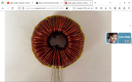
Screenshot from 2023-12-14 21:29:03.png

Description​

The magnetic ring is selected with an outer diameter of 47mm, an inner diameter of 24mm, a height of 18mm, and a magnetic permeability of 125 060 models.
The 77438 and 77439 series of iron-silicon-aluminum magnetic ring inductors are selected, which have the characteristics of high current and strong anti-saturation, low temperature rise in continuous operation at full current, gentle DC bias, and small high-frequency magnetic loss.
It is very suitable for SPWM inverter output filter inductors, power factor correction circuits (PFC inductors), DC/DC converter inductors, and grid-connected inverter filter inductors.
. 77438, 77439 series inductors

When the current is small and the inductance demand is large, choose the 77438 series; when the current is large and the inductance demand is small, choose the 77439 series; it can be customized according to the demand.
Inductor size: diameter (length): 55mm width (thickness): 28mm
Foot Spacing: 27mm

5MH/5A, wire diameter 1.0mm, 77438-133T


4MH/8A, wire diameter 1.2mm, 77438-119T


3MH/8A, wire diameter 1.2mm, 77438-103T


2.5MH/10A, wire diameter 1.4mm, 77438-94T


2MH/10A, wire diameter 1.4mm, 77438-84T


1MH/12A, wire diameter 1.5mm, 77439-86T


700UH/15A, wire diameter 1.6mm, 77439-72T


500UH/20A, wire diameter 1.4mm*2, 77439-60T


300UH/25A, wire diameter 1.6mm*2, 77439-47T


100UH/30A, wire diameter 1.4mm*3, 77439-27T

All series are not listed and can be customized according to customer inductance and current.
Introduction to the selection of magnetic core materials: Because the loss and anti-saturation performance of the magnetic powder core material are better than those of the iron powder core (commonly known as: yellow and white ring magnetic ring), and the iron powder core (yellow and white ring) generally can only work at medium and low frequencies (usually 5kHz). below, and the loss is large). Therefore, the magnetic ring inductors designed by our shop are all made of FeSiAl, high magnetic flux or MPP materials (international magnetic core brand CSC or Magnetics). The comprehensive cost performance of the inductors wound with FeSiAl magnetic cores is high; the inductances wound with high flux magnetic cores are small in size, but the price is higher; the inductances wound with MPP magnetic cores are second in volume and low in loss (FeSiAl, high The loss of magnetic flux is also relatively small), but it is expensive. All three materials can operate at harmonic frequencies up to 500kHz.
 
Nice find Sun Walker.
Do you have a price on those ?

I found the data sheet for the Magnetics 77439 bare cores.
https://www.datasheets.com/part-details/0077439a7-magnetics-37731238#package

Around 50 to 70 turns of the thickest wire that will fit should do nicely.
Or 25 to 35 turns around two cores stacked.

A quick internet search turned up these guys, ten 77439 cores for $60 U.S.
https://www.tzsupplies.com/toroidal-cores-magnetics-koolmu-77439a7-i3748603/

Winding your own will usually end up cheaper, but the ready wound ones more convenient if not too spendy.
Making your own also means you can use slightly thicker wire, to reduce heating and lower losses.
 
Do you have a price on those ?
AU$31.16
/ lot (2 Pieces) Free postage

High Power Inductor 100uH~1mH~5mH Grid-connected Inverter, PFC Coil​


Color: 100UH 30A
5MH 5A
4MH 8A
3MH 8A
2MH 10A
1MH 12A
700UH 15A
500UH 20A
300UH 25A
100UH 30A


There's about 3 stores selling them on
www.aliexpress.com, (I have just stated using Alibaba, cheaper than ebay, though I'm still waiting for my 1st purchases to arrive, they are in the country according to tracking).
Came up in a general search "High power inductor 100uH~1mH~5mH".

So I'll go ahead & buy some 300UH/25A.

Probably a good place to buy the cores aswell, if winding them.
 
Last edited:
A 20 amp commercial light dimmer choke will usually have an inductance of about 600 microhenries which would be ideal.
Hi, Just before I order the chokes, would I be better getting the 500UH/20A, wire diameter 1.4mm*2, rather than the 300UH/25A, wire diameter 1.6mm*2?
Same shop similar cost.
Higher Amps or higher uH?
 
It depends on what you are doing.
Higher uH inductance is ALWAYS better, as long as the rated current of the choke will not be exceeded.

If you work out your total combined solar panel power, and your battery voltage, that will give you the max theoretical charging current.
If its 20 amps or less (say 20A at 54 v = 1.08Kw) then go for the 20 amp choke.

If it works out to 25 amps at 54v = 1.35Kw go for the choke with fewer turns and thicker wire.

Don't stress yourself out over this, both will work.
 
Last edited:

MPPT ANALOGUE ~1KW Warpspeed

That's the search tittle of the file on easyeda..
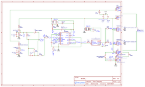
After many nights, I have (maybe)finished the 1st stage 3 more to go, (probably take as long, good learning process).
  1. Design your schematic. X
  2. Lay out your PCB.
  3. Fill out your BOM (Bill of Materials).
  4. Send the Gerber, BOM, and PNP files to JLCPCB for manufacture / assembly.
Schematic_MPPT ANALOGUE ~1KW Warpspeed 3_2024-01-09.png
Too enlarge use "view Image". Updated version.

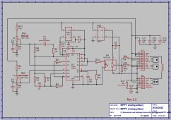
Analog MPPT circuit dia.jpg
A lot of time wasted searching for parts, but easyeda library is often out of date, choose Basic parts & use JLCPCB’s parts page instead of trying to do it through the Library. Its more up to date. I will need to buy some parts elsewhere & solder them in, not I/S = not in stock (may be a few more not I/S).
In theory if you log on to easyeda you should be able to find (see above tittle) & use it, but still not clear how that works.

Warpspeed, do you mind having a check of my above layout? Before I move to stage 2.

A Question;

Q. can I replace R4 with a potentiometer so I have an option of either a 12v batt or a 48v batt?
(13A, ~105v pv sys, 3 panels per string).
I think you said that low voltage (12v) won't work well, but then you used it as an example for choosing R4, just a thought.
 

Attachments

  • Schematic_MPPT ANALOGUE ~1KW Warpspeed_2023-12-17.png
    Schematic_MPPT ANALOGUE ~1KW Warpspeed_2023-12-17.png
    137.5 KB · Views: 23
  • Schematic_MPPT ANALOGUE ~1KW Warpspeed 2_2023-12-18.png
    Schematic_MPPT ANALOGUE ~1KW Warpspeed 2_2023-12-18.png
    136.4 KB · Views: 15
  • Schematic_MPPT ANALOGUE ~1KW Warpspeed 3_2023-12-19.png
    Schematic_MPPT ANALOGUE ~1KW Warpspeed 3_2023-12-19.png
    135.6 KB · Views: 23
Last edited:
Back
Top